Alloy powder mixing machine

An alloy powder and mixer technology, applied in mixers, mixers with rotating containers, mixer accessories, etc., can solve problems such as safety hazards, combustion, affecting the working environment of workshops, etc., to achieve production safety, reduce noise, and reduce temperature. Effect

Active Publication Date: 2016-07-06
LONGYAN TAIMEI WEAR RESISTANT ALLOY CO LTD
View PDF6 Cites 0 Cited by
  • Summary
  • Abstract
  • Description
  • Claims
  • Application Information

AI Technical Summary

Problems solved by technology

[0002] The mixer is a kind of equipment that mixes a variety of alloy powders evenly. It includes a mixing tank. The alloy powder is placed in the mixing tank. Steel balls are set in the mixing tank. When rotating at high speed, the steel ball is moved by the ribs, and the steel ball hits the powder to make the powder fully mixed evenly. However, there are two shortcomings in the prior art. 1. The mixing tank is a metal tank, and the mixing tank collides with the steel ball when rotating at high speed It produces huge noise pollution, seriously affects the working environment of the workshop, and has a great impact on the health of production workers without protective devices; 2. In order to prevent the powder from being oxidized, alcohol and other antioxidants are often added to the mixing tank. When the mixing tank is running without cooling down, sparks are likely to be generated during the impact of the internal steel balls, and the sparks are likely to cause alcohol to burn, thus creating a safety hazard. Therefore, a cooling device must be installed

Method used


Image

  • Alloy powder mixing machine
  • Alloy powder mixing machine
  • Alloy powder mixing machine

Examples


Embodiment Construction

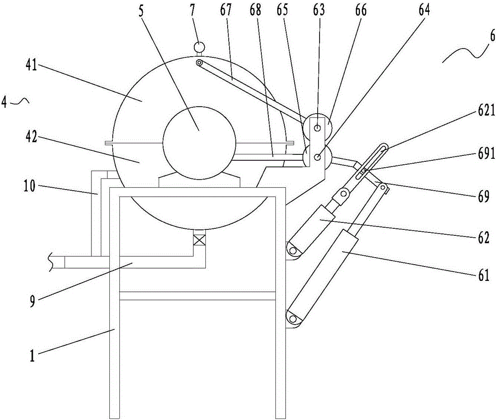
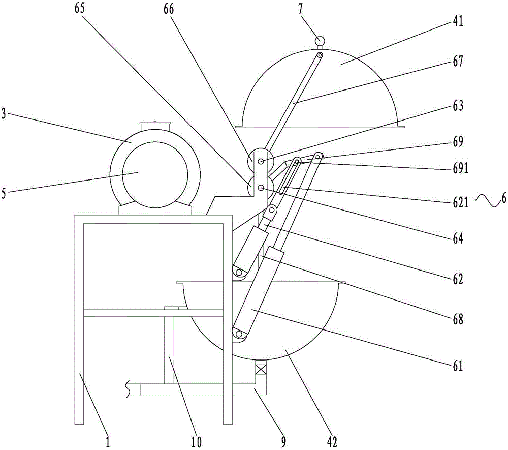
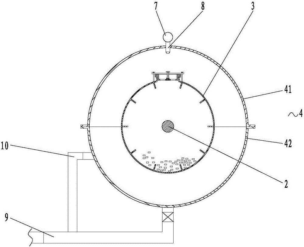
[0017] Such as Figure 1 to Figure 3 As shown in one of them, the present invention includes a frame 1, a main shaft 2, a mixing tank 3 and an outer cover 4, the main shaft 2 is rotatably connected to the frame 1, and is driven to rotate by a reduction motor 5, and the mixing tank 3 is fixedly sleeved on the main shaft 2 , and rotate synchronously with the main shaft 2, the outer cover 4 is located outside the mixing tank 3 and surrounds the mixing tank 3; the outer cover 4 includes an upper cover body 41 and a lower cover body 42, and the frame 1 is provided with a driving upper cover body 41 , the driving device 6 for closing or opening the lower cover body 42; the top of the upper cover body 41 is provided with a water inlet pipe 7, and the bottom of the water inlet pipe 7 is provided with a plurality of spray heads 8 extending into the upper cover body 41, and more Two shower heads 8 are arranged at equal intervals along the length direction of the water inlet pipe 7, and ...


PUM


Abstract

The invention discloses an alloy powder mixing machine comprising a rack, a main shaft, a mixing tank and an outer cover, wherein the main shaft is rotationally connected to the rack and is driven by a speed reducing motor to rotate; the mixing tank fixedly sleeves the main shaft and synchronously rotates together with the main shaft; the outer cover is arranged outside the mixing tank and is used for surrounding the mixing tank; the outer cover comprises an upper cover body and a lower cover body; the rack is provided with a driving device for driving the upper cover body and the lower cover body to be closed or opened; and the top of the upper cover body is provided with a water inlet pipe, the bottom of the water inlet pipe is provided with a plurality of spray heads extending into the upper cover body, the water inlet end of the water inlet pipe is connected with a water storage tank through a water pump, the bottom of the lower cover body is provided with a water outlet connected with a water outlet pipe, the water outlet pipe is provided with a valve, an overflow port is formed in the middle of the lower cover body and is connected with an overflow pipe, and the water outlet ends of the overflow pipe and the water outlet pipe are respectively connected with the water storage tank. The mixing machine disclosed by the invention has the advantages of low noise, production safety, high production quality and the like.

Description

technical field [0001] The invention relates to the field of mixers, in particular to an alloy powder mixer. Background technique [0002] The mixer is a kind of equipment that mixes a variety of alloy powders evenly. It includes a mixing tank. The alloy powder is placed in the mixing tank. Steel balls are set in the mixing tank. When rotating at high speed, the steel ball is moved by the ribs, and the steel ball hits the powder to make the powder fully mixed evenly. However, there are two shortcomings in the prior art. 1. The mixing tank is a metal tank, and the mixing tank collides with the steel ball when rotating at high speed It produces huge noise pollution, seriously affects the working environment of the workshop, and has a great impact on the health of production workers without protective devices; 2. In order to prevent the powder from being oxidized, alcohol and other antioxidants are often added to the mixing tank. When the mixing tank is running without cooling...

Claims


Application Information

Patent Timeline
IPC IPC(8): B22F1/00B01F9/02B01F15/00B01F29/60
CPCB22F1/0003B01F29/60B01F35/2215B01F35/32045B01F35/3211B01F35/454B01F35/43B01F2035/98B01F35/92
Inventor 王彦祥于彦爽王增良
Owner LONGYAN TAIMEI WEAR RESISTANT ALLOY CO LTD
Why Eureka
Try Eureka