Method for enhancing strength of cutting edge of tool through additive manufacturing technology

A technology for additive manufacturing and cutting tools, which is applied in the directions of additive manufacturing, additive processing, and process efficiency improvement. It can solve the problems of unusable tools, waste of raw materials, tool wear, etc. The effect of increasing the service life

Inactive Publication Date: 2016-07-06
SHENYANG AIRCRAFT CORP
View PDF4 Cites 3 Cited by
  • Summary
  • Abstract
  • Description
  • Claims
  • Application Information

AI Technical Summary

Problems solved by technology

[0002] At present, most of the common knives used on the market are made of common tool steel. During use, the cutting edge is easily blunted, especially when processing difficult-to-machine metals such as titanium alloys. Due to the insufficient strength of the cutting edge, the cutting edge is easily damaged Annealing due to frictional heat during processing makes processing difficult or impossible; even if this kind of tool is used to process ordinary and easy-to-process carbon steel, due to the large amount of heat generated during processing, it is also easy to cause partial annealing of the tool edge
[0003] The currently used special cutting tools are generally made of cemented carbide integral sintering, which is relatively expensive, not only wastes raw materials, but also is prone to brittle fracture because the material is very hard and brittle; during use, due to improper operation or the characteristics of the cutting part material A certain degree of wear or local chipping damage will occur to the tool, making the tool unusable, and it can only be scrapped if it is serious

Method used


Image

  • Method for enhancing strength of cutting edge of tool through additive manufacturing technology
  • Method for enhancing strength of cutting edge of tool through additive manufacturing technology
  • Method for enhancing strength of cutting edge of tool through additive manufacturing technology

Examples


Embodiment 1

[0028] Embodiment 1 common milling cutter, wear milling cutter

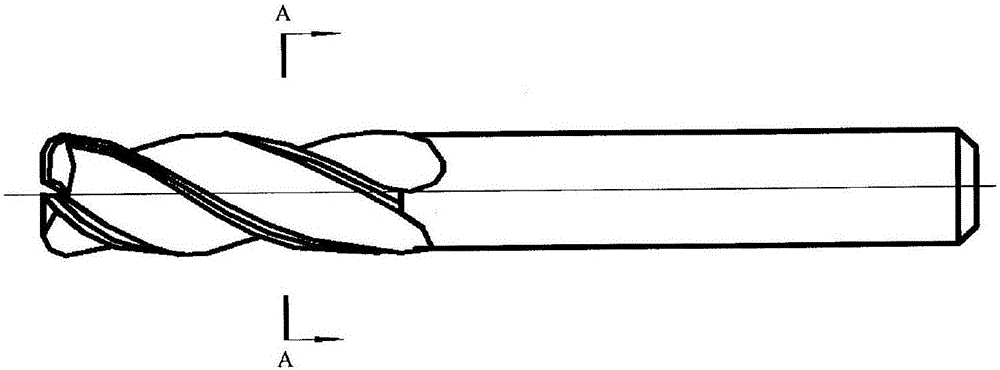
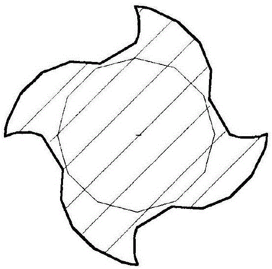
[0029] First, the working edge (side edge and end edge) of the tool is evenly removed by O.8mm-1.5mm to form a basic platform, and the surface of the platform is perpendicular to the cutting direction of the tool. Figure 2b and Figure 3b shown; clean the oil, dust, water and other dirt on the surface of the tool, and wait for use; establish a digital model according to the size and shape of the tool, the size of the removed part, and the size of the platform left on the tool after the tool edge is removed, that is, Based on the remaining surface on the cutter body, use CATIA or CAD software to draw the part diagram for forming,

[0030] The size of the bottom surface of the new figure is to increase 0.5mm in all directions on the basis of the bottom surface of the original foundation, and the bottom surface is a plane or a helical surface along the axis direction of the knife. The outer surface size of the fo...

Embodiment 2

[0031] Embodiment 2 Drill bit

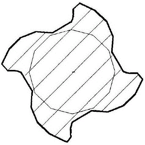
[0032] Since the working part of the drill is the front end and the front side edge of the drill, not all the side edges, when the drill is reinforced, it is not necessary to reinforce all the side edges of the drill, and only the front part of the side edge is reinforced. Can. like Figure 4 Shown is the state of the drill bit after reinforcement; Figure 5 It is the A-A view of the drill bit after reinforcement, and the shape and surface of the cutting edge after reinforcement;

[0033] The main working edge of the tool: the end edge and part of the side edge (about 15mm-20mm from the front end) are uniformly removed by 1.0mm-1.5mm, and a basic platform is established. The surface of the platform is perpendicular to the cutting direction of the tool, and the platform is in line with the unprocessed The cutting edge becomes a beveled transition; clean the oil, dust, water and other dirt on the surface of the tool for use; establish a digital...

Embodiment 3

[0034] The cutting tool of embodiment 3 chipping

[0035] For a tool with continuous chipping in multiple places, the cutting edge of the tool is polished as a whole according to the largest chipping size, and the foundation for repair is made, and then repaired by laser powder feeding additive manufacturing process; a tool with less than three and discontinuous chipping If the cutting tool with a sharp edge should be ground and cleaned, according to the size of the grinding place, use CATIA or CAD software to draw an area map for forming (the method is the same as in Example 1), which is the digital model for forming. Compile the repair program and use the laser powder feeding additive manufacturing process to repair; the repaired knives can be used again after mechanical sharpening, saving a lot of cost.


PUM


Abstract

The invention discloses a method for enhancing the strength of a cutting edge of a tool through an additive manufacturing technology. The method comprises the steps that 1, the work cutting edge of the tool is evenly removed by 0.8 mm to 1.5 mm, a basic platform is formed, and the surface of the basic platform is perpendicular to the cutting direction of the tool; 2, a digital model is established according to the dimension and shape of the tool, the dimension of the removed part and the dimension of the platform reserved on the tool after the cutting edge of the tool is removed; 3, programming is carried out according to the digital model and programming language of machining equipment; 4, the tool is clamped on a workbench of the machining equipment, the machining equipment is adjusted, a coaxial powder conveying work head of the machining equipment exactly faces the additive forming position of the tool, forming is called to start additive manufacturing work, and formed height is 0.5 mm larger than the height of the removed part; and 5, after forming is finished, the tool is mounted on a numerical control tool sharpener, and grinding is carried out again according to original grinding forming. According to the method, the service life of the tool can be prolonged, production efficiency can be improved, cost can be reduced, and good application prospects are achieved.

Description

technical field [0001] The invention belongs to the field of additive manufacturing, and in particular relates to a method for enhancing the edge strength of a tool by using additive manufacturing technology, which is used for enhanced manufacturing and repair and reinforcement of the tool. Background technique [0002] At present, most of the common knives used on the market are made of common tool steel. During use, the cutting edge is easily blunted, especially when processing difficult-to-machine metals such as titanium alloys. Due to the insufficient strength of the cutting edge, the cutting edge is easily damaged Annealing due to frictional heat during processing makes processing difficult or impossible; even if this kind of tool is used to process ordinary and easy-to-process carbon steel, due to the large amount of heat generated during processing, it is also easy to cause partial annealing of the tool edge. [0003] The currently used special cutting tools are gener...

Claims


Application Information

Patent Timeline
Patent Type & Authority Applications(China)
IPC IPC(8): B22F7/06B22F3/105B33Y10/00
CPCB22F7/062B33Y10/00B22F2007/068B22F10/00B22F10/66B22F12/50B22F10/25Y02P10/25
Inventor 杨磊高郑宇
Owner SHENYANG AIRCRAFT CORP
Why Eureka
Try Eureka