A vacuum pump tail gas anti-static, fireproof, explosion-proof conveying device

A conveying device, anti-static technology, applied in explosion-proof conveying device, vacuum pump tail gas anti-static, fire protection field, can solve the problem of static inflammability and explosion, and achieve the effect of reducing the content of organic solvent and good support and fixation

Active Publication Date: 2018-01-30
SHANDONG KANBO BIOCHEM TECH
View PDF7 Cites 0 Cited by
  • Summary
  • Abstract
  • Description
  • Claims
  • Application Information

AI Technical Summary

Problems solved by technology

In order to effectively solve the problem of electrostatic flammability and explosion in the process of conveying the tail gas of the vacuum pump to the incinerator

Method used


Image

  • A vacuum pump tail gas anti-static, fireproof, explosion-proof conveying device
  • A vacuum pump tail gas anti-static, fireproof, explosion-proof conveying device
  • A vacuum pump tail gas anti-static, fireproof, explosion-proof conveying device

Examples


Embodiment 1

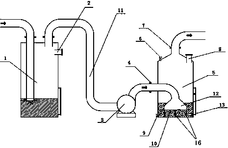
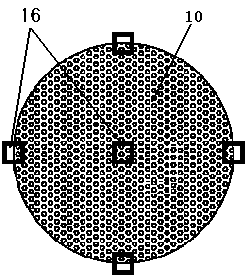
[0023] Embodiment 1, the present invention includes a water-sealed tank 1, an explosion-proof fan 3, and a water-washing tank 5. A first burst disc 2 is provided on the upper right side of the water-sealed tank 1, and a pipeline 11 is provided on the top right side of the water-sealed tank 1. The right side of water seal tank 1 is connected with explosion-proof fan 3 by pipeline 11, is connected to the bottom of water washing tank 5 by pipeline 11 on the right side of explosion-proof fan 3, forms gas pipeline 12, between explosion-proof fan 3 and water washing tank 5 A gas inlet 4 is provided on the pipeline 11 between them, a liquid inlet 6 is provided on the upper left side of the water washing tank 5, a second burst disc 8 is provided on the upper right side of the water washing tank 5, and a second bursting disc 8 is provided on the top pipe 11 of the water washing tank 5. There is a gas outlet 7, a porous sieve plate 10 is provided at the bottom of the washing tank 5, a li...

Embodiment 2

[0034] Embodiment 2: in combination with image 3 and 4 , the present invention is further described:

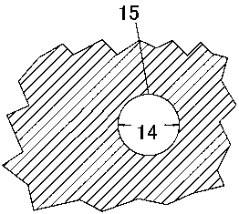
[0035] The vacuum tail gas to be treated contains 20% methanol and 80% air, which is divided into numerous bubbles with a diameter of 1cm by the sieve plate in the washing tank, and the methanol gas in the bubbles passes through the spherical surface to the water. The spherical surface of the bubble is a stable interface, and there is a very thin stagnation film 15 on both sides of the interface. Methanol passes through the inner gas film 15.1 and the outer liquid film 15.2 in the form of molecular diffusion, and enters the main body of the liquid phase from the gas phase.

[0036] At the phase interface, the gas and liquid phases reach equilibrium, and in the main body of the gas and liquid phases outside the two stagnant films of the gas film and the liquid film, due to the sufficient turbulence of the fluid, the material composition is uniform.

[0037] After the above-...


PUM


Abstract

The invention relates to a vacuum pump tail gas anti-static, fireproof and explosion-proof conveying device and a method. The device is characterized in that a pipe is arranged at the top of the right side of a water sealing tank; the right side of the water sealing tank is connected with an explosion-proof fan through the pipe; the right side of the explosion-proof fan is connected to the lower part of a water washing tank through a pipe to form a gas pipeline; a gas inlet is formed in the pipe between the explosion-proof fan and the water washing tank; a liquid inlet is formed in the left side of the upper part of the water washing tank; a gas outlet is formed in a top pipe of the water washing tank; a porous screen plate is arranged at the bottom of the water washing tank; and a liquid outlet is formed in the left side of the lower part of the water washing tank. The vacuum pump tail gas anti-static, fireproof and explosion-proof conveying device and method have the following beneficial effects: the vacuum pump tail gas anti-static, fireproof and explosion-proof conveying is realized; treated vacuum pump tail gas largely reduces the content of organic solvent; and mixed gas originally located in an explosion limit range is treated by a mixed gas absorbing device through the water washing tank to locate below the explosion limit, so that the safety is guaranteed.

Description

technical field [0001] The invention relates to a vacuum pump tail gas conveying device, in particular to a vacuum pump tail gas antistatic, fireproof and explosion-proof conveying device. Background technique [0002] With the increasingly serious situation of air pollution and the stricter implementation of environmental protection laws, the vacuum exhaust gas in the chemical production process is also included in the scope of governance, which must be treated in a harmless manner before it can be discharged, and the exhaust gas of vacuum pumps often contains a certain amount of organic solvents. And air, once the static electricity accumulates to a certain extent during the transportation process, there will be a danger of combustion and explosion. If the exhaust gas of the vacuum pump is to be treated harmlessly, it needs to be transported to the incinerator for high-temperature combustion and decomposition. In order to effectively solve the problem of static inflammabi...

Claims


Application Information

Patent Timeline
Patent Type & Authority Patents(China)
IPC IPC(8): F17D1/02F17D5/00B01D53/18B01D53/22F04B39/00
CPCB01D53/1487B01D53/18B01D53/228B01D53/229B01D2053/222B01D2252/103B01D2257/704F04B39/00F17D1/02F17D5/005
Inventor 李建新李建彬徐松波
Owner SHANDONG KANBO BIOCHEM TECH
Why Eureka
Try Eureka