Accelerating projectile support and method for non-empennage projectile body

A projectile and tail technology, which is applied in the direction of ammunition, ammunition testing, weapon accessories, etc., can solve the problems that the processing technology cannot meet the requirements, affect the attitude of the projectile hitting the target, interfere or be inseparable, and reduce the test cost. , Good target attitude, reducing the effect of processing difficulty

Active Publication Date: 2016-07-06
BEIJING INSTITUTE OF TECHNOLOGYGY
View PDF4 Cites 12 Cited by
  • Summary
  • Abstract
  • Description
  • Claims
  • Application Information

AI Technical Summary

Problems solved by technology

The integrated bullet holder structure often needs to adopt an additional unloading device to separate the bullet holder before the projectile hits the target body. This is because the cost is high, and the second is that the separation effect may not be good; Additional unloading device, but the processing is complicated and the process re

Method used


Image

  • Accelerating projectile support and method for non-empennage projectile body
  • Accelerating projectile support and method for non-empennage projectile body
  • Accelerating projectile support and method for non-empennage projectile body

Examples


Embodiment 1

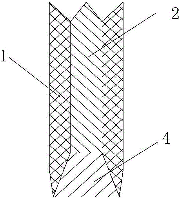
[0014] Embodiment 1, referring to the accompanying drawings, a tailless projectile acceleration bullet rest, comprising: a bullet rest main body 1 and a bottom pusher 4;

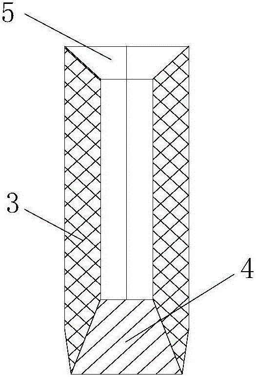
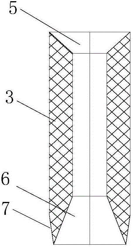
[0015] The main body 1 of the bullet holder is a circular tube formed by gluing the wall surfaces of 2 to 4 clips 3, and its length is 5 to 10 mm longer than that of the projectile; The central angle is 180 degrees at the same time, the central angle is 120 degrees when there are 3 clips 3, and the central angle is 90 degrees when there are 4 clips 3; Make it tightly fit in the launch barrel to play the role of air-holding; the inner diameter of the clip 3 is a negative tolerance, slightly smaller than the diameter of the projectile 2, so that the projectile 2 is tightly restrained inside the clip 3 without shaking to generate an angle of attack; The inner surface 5 of the head of the card valve 3 is an inverted conical surface; the inner surface 6 of the bottom is a right conical surface; the outer surface ...

Embodiment 2

[0020] Embodiment 2, a kind of tailless projectile acceleration method, it uses the non-finned projectile described in embodiment 1 to accelerate the bullet holder, and adopts 10mm~30mm launch barrel, 4 / 7 stone gunpowder or high-pressure gas, to large length The diameter ratio of the tailless projectile 2 accelerates.


PUM

PropertyMeasurementUnit
Tensile yield strengthaaaaaaaaaa
Densityaaaaaaaaaa
Wall thicknessaaaaaaaaaa

Abstract

The invention belongs to the technical field of ballistic tests and particularly relates to the projectile high-speed loading technology. According to the technical scheme, an accelerating projectile support for a non-empennage projectile body comprises a projectile support body (1) composed of 2-4 clamping petals in a sticking manner and a bottom pusher (4). Stable loading and launching of a launching body tube with the length ranging from 10 mm to 30 mm are adopted for the non-empennage projectile body with the length-diameter ratio ranging from 3 to 7, reliability of high-speed loading tests of the projectile body is improved, and the test cost is lowered. Stretching of the clamping petals and stable separation between the projectile body and the clamping petals are achieved in the projectile flying process through aerodynamic force and an inverted-conical structure at the front end, and a good target touching posture of the projectile body is ensured while the machining difficulty is lowered. Due to the rigid bottom pusher, it is ensured that the projectile body cannot be seated backwards when being launched, chamber pressure directly acts on the bottom pusher, the bottom pusher pushes the projectile support to move through a positive conical face and pushes the projectile body to move through an upper surface, it can be avoided that angles of attack are generated during fragment flying, and damage to the launching body tube can also be reduced; and good universality is achieved.

Description

technical field [0001] The invention belongs to the technical field of ballistic testing, in particular to the high-speed loading technology of projectiles. Background technique [0002] Loading the projectile to a high speed to achieve a high-speed impact on the target is a key technology in the research on the penetration effect of the projectile and the dynamic mechanical behavior of the Taylor rod. Commonly used loading methods include two-stage light gas guns, ballistic guns, etc. The projectile body is loaded by the high-pressure gas force at the bottom in the barrel. The bullet holder is an important part to realize loading. Its main function is to Drive and guide the movement of the projectile to achieve a higher speed and at the same time ensure that the projectile does not deflect in the bore, avoid the occurrence of phenomena such as slashing, and at the same time ensure that the projectile maintains a good flight attitude in the initial stage after it is released...

Claims


Application Information

Patent Timeline
IPC IPC(8): F42B35/00
CPCF42B35/00
Inventor 徐豫新王绪财任杰王树山王伟
Owner BEIJING INSTITUTE OF TECHNOLOGYGY
Why Eureka
Try Eureka