Pipeline laser washing device based on curved surface holophote

A curved surface mirror and laser cleaning technology, which is applied in the field of laser cleaning, can solve the problems of unable to clean the surface of the pipeline, slow cleaning speed, easy to damage the pipeline, etc., and achieve the effect of convenient automatic operation, high cleaning efficiency and high cleanliness

Active Publication Date: 2016-07-13
HUAZHONG UNIV OF SCI & TECH
View PDF6 Cites 10 Cited by
  • Summary
  • Abstract
  • Description
  • Claims
  • Application Information

AI Technical Summary

Problems solved by technology

[0005] Aiming at the defects of the prior art, the object of the present invention is to provide a laser cleaning equipment capable of cleaning pipelines, aiming to solve the problem that the cleaning equipment in the prior art cannot clean the surface of the pipeline, easily damage the pipeline, slow cleaning speed, low efficiency, and energy consumption. many technical issues

Method used


Image

  • Pipeline laser washing device based on curved surface holophote
  • Pipeline laser washing device based on curved surface holophote
  • Pipeline laser washing device based on curved surface holophote

Examples


Embodiment 1

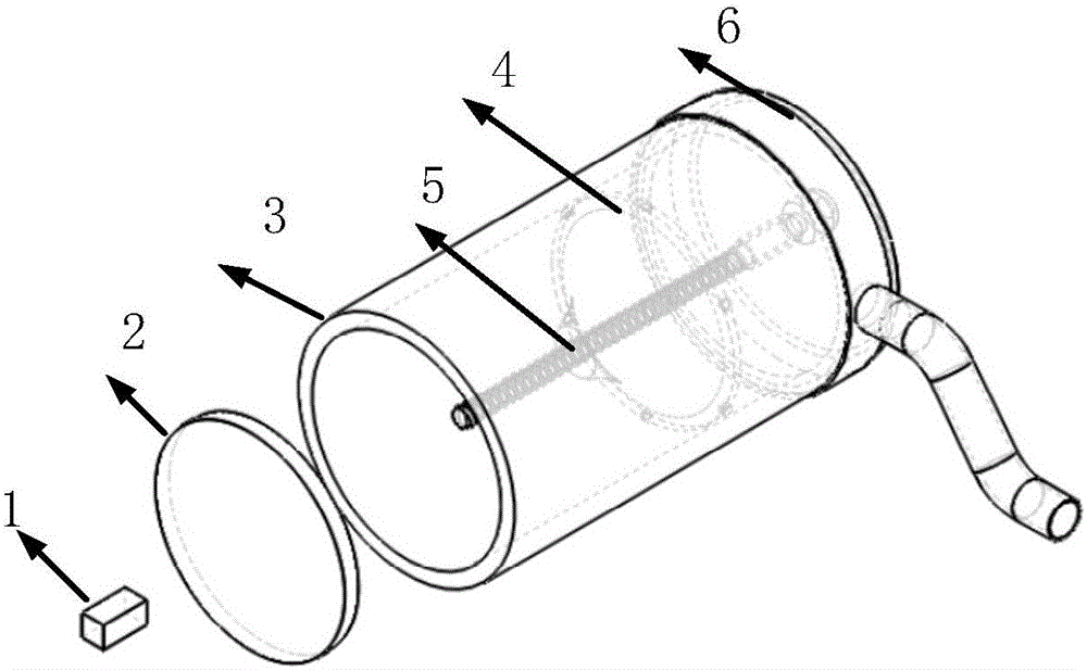
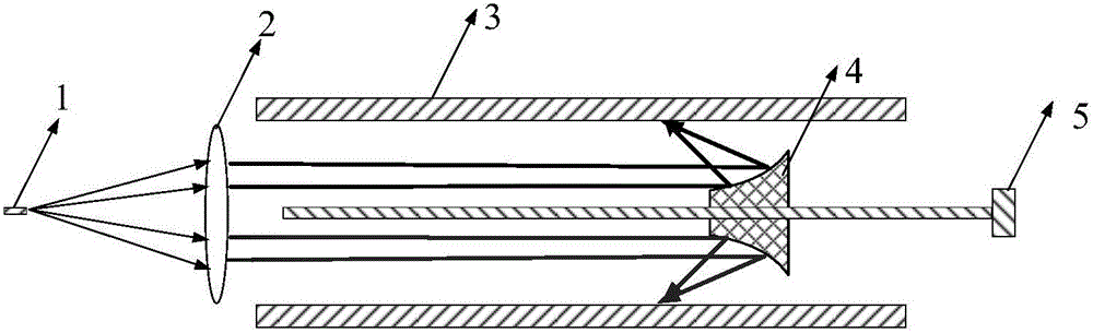
[0031] Such as figure 1As shown, the center of the laser 1, the lens system 2, and the curved total reflection mirror 4 are on the same straight line, the first direction is from the center of the curved mirror 4 to the center of the laser 1, and the second direction is the opposite direction. The curved surface reflector 4 is connected with the screw mandrel of the motor 5, so that when the screw mandrel rotates clockwise, the curved surface total reflection mirror 4 moves along the first direction, and when the screw mandrel rotates counterclockwise, the curved surface total reflection mirror 4 moves along the second direction. sports. The laser 1 is at a certain distance from the lens system 2, so that the laser light with a certain divergence angle emitted by the laser 1 can be collimated by the lens system 2. The lens system 2 is composed of one lens or multiple lenses, which are determined according to the required energy density and pass through the lens system. 2. The...

Embodiment 2

[0038] The laser 1, the lens system 2, and the center of the curved total reflection mirror 4 are on the same straight line, the first direction is from the center of the curved total reflection mirror 4 to the center of the laser 1, and the opposite direction is the second direction. The curved total reflection mirror 4 is connected with the motor 5 so that when the motor drives the screw mandrel to rotate clockwise, the curved surface total reflection mirror 4 moves along the first direction, and when the motor drives the screw mandrel to rotate counterclockwise, the curved surface total reflection mirror 4 moves along the first direction. Movement in two directions. The laser 1 is located at a certain distance from the lens system 2, so that the laser light with a certain divergence angle emitted by the laser 1 can be collimated by the lens system 2. The lens system 2 is composed of one lens or multiple lenses, which are determined according to the required energy density an...


PUM


Abstract

The invention provides a pipeline laser washing device based on a curved surface holophote.The pipeline laser washing device comprises a laser, a lens system, the curved surface holophote and a motor, and the centers of the laser, the lens system, the curved surface holophote and the motor are located on the same straight line; the laser and the lens system are spaced by a certain interval so that laser light emitted by the laser can be collimated by the lens system, and light collimated by the lens system changes into annular parallel light entering the curved surface holophote in a parallel incident mode; the curved surface holophote is connected with a lead screw of the motor so that the curved surface holophote can move in the first direction when the lead screw rotates clockwise, and the curved surface holophote can move in the second direction when the lead screw rotates counterclockwise.By means of an optical shaping system and a parabolic reflector, the focus point of the emitted laser light can be located on the surface of a pipeline, and accordingly high unit area power can be acquired with low average power, pollutants evaporate, gasify or decompose instantly, and the heat conduction loss is reduced.The emitted laser light is annular focusing light and is high in pipeline washing efficiency.

Description

technical field [0001] The invention belongs to the technical field of laser cleaning, and more specifically relates to a pipeline laser cleaning device based on a curved total reflection mirror. Background technique [0002] There are four main types of traditional cleaning methods: high-pressure water cleaning, mechanical cleaning, chemical cleaning and ultrasonic cleaning. These cleaning methods are mainly used to remove surface pollutants mixed with particles based on rust and grease, and meet the needs of existing industrial production and daily life to a large extent. [0003] However, traditional cleaning methods are usually accompanied by high pollution, high consumption, low cleaning efficiency, and may even damage the equipment that needs to be cleaned. Under the requirements of environmental protection and high precision, the application of cleaning technology is greatly restricted, which also brings great challenges to the development of cleaning industry worldw...

Claims


Application Information

Patent Timeline
Patent Type & Authority Applications(China)
IPC IPC(8): B08B7/00B23K26/064
CPCB08B7/0042B23K26/0643
Inventor 朱广志周业波朱晓王海林齐丽君宋恩茂
Owner HUAZHONG UNIV OF SCI & TECH
Why Eureka
Try Eureka