Method for enhancing hard turning circularity of thin-wall annular parts

A technology of hard turning and circular ring, which is applied in the direction of bearing components, shafts and bearings, mechanical equipment, etc., can solve the problems of triangle roundness error contour, affecting machining accuracy, multiple clamping, etc., to improve the roundness of turning, Achieve high-precision manufacturing and prevent radial deformation

Inactive Publication Date: 2016-07-13
SHANGHAI JIAO TONG UNIV +1
View PDF4 Cites 4 Cited by
  • Summary
  • Abstract
  • Description
  • Claims
  • Application Information

AI Technical Summary

Problems solved by technology

The precision hard turning process of bearing rings generally uses a three-jaw chuck for clamping and positioning. Taking the inner ring of a bearing as an example, first locate the outer diameter and end face, hard turn the inner diameter and the other end face, and then use the hard turned inner diameter and end face for positioning , precision hard turning outer diameter, end face and groove, and the bearing ring is a thin-walled circular part with poor rigidity. During the clamping process and cutting process, it is very easy to produce large radial deformation due to clamping force and cutting force, which seriously affects Machining accuracy, which in turn affects bearing assembly accuracy and service life
In this processing technology, each ferrule is clamped and positioned twice, which introduces positioning errors. At the same time, a three-jaw chuck is used for clamping. After processing, the channel is prone to triangular roundness error contours, which affects processing accuracy.
[0003] In summary, due to the insufficient rigidity of the bearing ring, the current hard turning process has relatively prominent technical and quality problems in the clamping method and processing technology
Therefore, it is very urgent and necessary to study and invent a new processing technology for bearing rings, to overcome the problems of multiple clamping, clamping and large processing deformation in the existing hard turning processing technology, and to realize high-precision manufacturing of bearings.

Method used


Image

  • Method for enhancing hard turning circularity of thin-wall annular parts
  • Method for enhancing hard turning circularity of thin-wall annular parts
  • Method for enhancing hard turning circularity of thin-wall annular parts

Examples


Embodiment 1

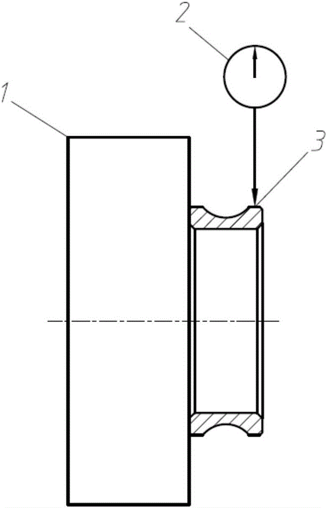
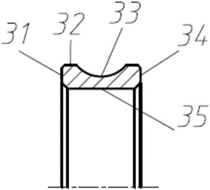
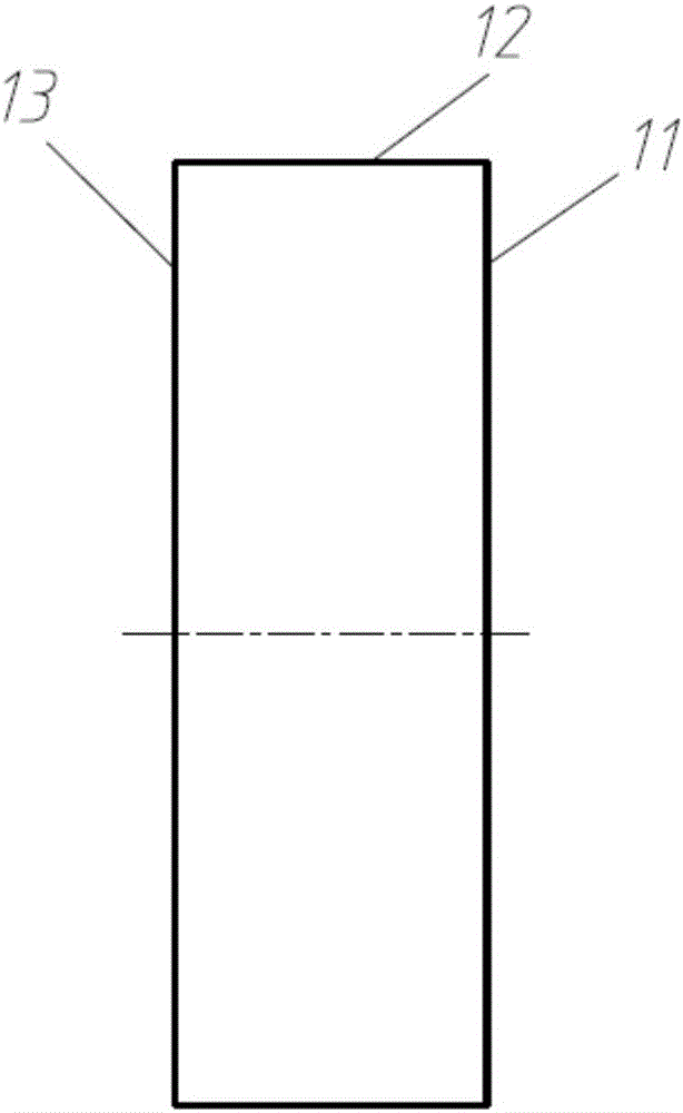
[0039] refer to Figure 1-4 , in this embodiment, the thin-walled annular parts are the inner ring 3 of a single row angular contact ball bearing, including a positioning end face 31, an outer circular surface 32, an outer groove or outer raceway 33, a non-locating end face 34, and an inner circular surface 35 ; The fixture is a magnetic chuck 1, including a clamping positioning surface 11, an outer circular surface 12, and a surface 13 connected with the lathe spindle head.

[0040] The machining of the inner ring 3 of the single row angular contact ball bearing includes the following steps:

[0041] 1. Prepare the inner ring 3 with machining allowance.

[0042] 2. Perform quenching and tempering heat treatment on the inner ring 3 with machining allowance.

[0043] Among them, the inner ring 3 of the single row angular contact ball bearing is made of GCr15 bearing steel, which is subjected to normal quenching and tempering heat treatment. After heat treatment, the hardness ...

Embodiment 2

[0050] refer to Figure 3-6 , in this embodiment, the thin-walled annular parts are the outer ring 4 of a single row angular contact ball bearing, including a positioning end face 41, an outer circular surface 42, a non-locating end face 43, an inner circular surface 44, an inner raceway or an inner groove 45 ; The fixture is a magnetic chuck 1, including a clamping positioning surface 11, an outer circular surface 12, and a surface 13 connected with the spindle head of the lathe.

[0051] The machining of the outer ring 4 of the single row angular contact ball bearing includes the following steps:

[0052] 1. Prepare the outer ring 4 with machining allowance.

[0053] 2. Perform quenching and tempering heat treatment on the outer ring 4 with machining allowance.

[0054] Wherein, the material of the outer ring 4 is GCr15 bearing steel, which is subjected to normal quenching and tempering heat treatment. After the heat treatment, the hardness of the outer ring 4 should be hi...


PUM

PropertyMeasurementUnit
surface smoothnessaaaaaaaaaa

Abstract

The invention discloses a method for enhancing the turning circularity of cylindrical surfaces of thin-wall annular parts by controlling flatness of end faces of the thin-wall annular parts and flatness of work faces of clamping positioning pieces of the thin-wall annular parts. The method is characterized in that a positioning manner adopts the combination of end planar location and cylindrical surface dial gauge centering, and a clamping manner adopts the axial clamping of a magnetic chuck or a vacuum chuck. Compared with a manner with a three-jaw chuck for positioning and clamping, the method for positioning, clamping and processing disclosed by the invention can be used for processing the external cylindrical surface, the internal cylindrical surface, the end surfaces and annular channels in the internal and external cylindrical surfaces of the thin-wall annular parts with one clamping and positioning, effectively preventing radial deformation of the thin-wall annular parts during the clamping and processing process, and remarkably improving the turning circularity of the thin-wall annular parts, thereby providing an effective method for ultraprecise turning of thin-wall annular parts such as bearing rings.

Description

technical field [0001] The invention relates to the technical field of mechanic's circular ring parts, in particular to a method for improving the hard turning roundness of thin-walled circular ring parts. Background technique [0002] Bearing is a basic component widely used in mechanical and electronic products. It generally consists of outer ring, inner ring, rolling elements and cage. Bearing outer ring and inner ring are collectively referred to as bearing rings. They are typical thin-walled circular parts. The processing technology usually used is: blank forming (forging or pipe fittings)→annealing→turning or cold rolling→quenching, tempering→grinding Cut → super fine grinding. Grinding generally includes face grinding, cylindrical or internal grinding, and raceway centerless grinding. The multi-pass grinding process is costly and inefficient, and improper control of process parameters can easily cause ring grinding burns, produce surface deterioration layers, and s...

Claims


Application Information

Patent Timeline
Patent Type & Authority Applications(China)
IPC IPC(8): B23B1/00B23P15/00
CPCB23B1/00B23B2215/12B23P15/00
Inventor 姚振强张冏孙姚飞陈有光刘红宇刘亮王继江
Owner SHANGHAI JIAO TONG UNIV
Why Eureka
Try Eureka