Flying vehicle image pickup positioning method

A positioning method and aircraft technology, applied in the field of aircraft control, can solve problems such as being susceptible to interference, requiring high computing power for autonomous landing systems, and complex positional relationships of aircraft, and achieving the effect of increasing the probability of laser target sources

Active Publication Date: 2016-07-13
CSSC SYST ENG RES INST
View PDF9 Cites 23 Cited by
  • Summary
  • Abstract
  • Description
  • Claims
  • Application Information

AI Technical Summary

Problems solved by technology

[0006] However, there are many shortcomings in the above-mentioned technology: 1. The radio navigation equipment is complex and susceptible to interference; 2. Artificial visual control is insufficient in anti-cloudy, rainy, foggy and inclement weather, and it is prone to operational errors; The requirements are high; 4. The landing platform may be a moving platform, and the moving platform moves with six degrees of freedom, and the relationship between the position of the aircraft relative to the moving platform is complicated

Method used


Image

  • Flying vehicle image pickup positioning method
  • Flying vehicle image pickup positioning method
  • Flying vehicle image pickup positioning method

Examples


Embodiment Construction

[0054]Preferred embodiments of the present invention will be specifically described below in conjunction with the accompanying drawings, wherein the accompanying drawings constitute a part of the application and are used together with the embodiments of the present invention to explain the principles of the present invention.

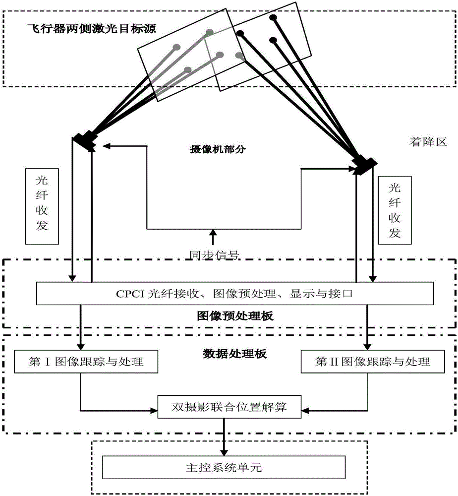
[0055] Such as figure 1 Shown, a kind of aircraft camera location method comprises the following steps:

[0056] Step 1. Four laser target sources installed on both sides of the upper fuselage of the aircraft in an approximately convex quadrilateral shape emit laser light under electrical control of the laser target source electric control box; the laser target sources installed in an approximately convex quadrilateral In image forming, it is convenient to use convex quadrilateral geometric relationship algorithm to identify the corresponding target source image and make correspondence in settlement;

[0057] The laser target source is a laser diode wi...


PUM


Abstract

The invention relates to a flying vehicle image pickup positioning method, which comprises the following steps that four laser target sources which are arranged at two sides of a machine body of a flying vehicle and are in approximate convex quadrilateral arrangement give out laser under the condition that a laser target source electric control box performs laser electric control; two near infrared wide-angled cameras are symmetrically arranged at the left side and the right side on a landing platform along the flying vehicle landing direction and are used for imaging the flying vehicle; through an optical fiber communication module, two paths of serial digital image signals are sent to an image processing unit; the image processing unit performs target source detection analysis and target source detection analysis post processing on the received two paths of serial digital image signals; a main control system unit calculates the flying vehicle moving direction according to the calculation result sent by the image processing unit and converts the flying vehicle moving direction into a control signal; the control signal is sent to the flying vehicle; the flying vehicle landing track is controlled. The defects of the existing positioning method are overcome; the operation is easy; the anti-jamming capability is high; the adaptability to severe environment is realized.

Description

technical field [0001] The invention relates to the technical field of aircraft control, in particular to an aircraft camera positioning method. Background technique [0002] At present, the aircraft landing positioning methods mainly include the following forms: [0003] Microwave landing guidance, the guidance data is obtained by the on-board equipment. Its advantages are: the system has high precision and can meet the requirements of all-weather work; it allows the aircraft to choose the airport flight path arbitrarily, and is suitable for various types of aircraft for various take-offs and landings; The requirement of increased traffic volume; the equipment is small in size and has low requirements on the site. But susceptible to electronic interference. [0004] Visual guidance, a full-time guide uses signal flags or radio instructions to visually guide the aircraft to land on the landing platform. This requires the instructor to have both rich command experience and...

Claims


Application Information

Patent Timeline
Patent Type & Authority Applications(China)
IPC IPC(8): G01C21/00G01C21/20G06T7/00
CPCG01C21/00G01C21/20G06T2207/10016
Inventor 姜广文赵辉朱永丽许涛
Owner CSSC SYST ENG RES INST
Why Eureka
Try Eureka