A Controllable Hybrid Electromagnetic Coupling Substrate Integrated Waveguide Filter
What is Al technical title?
Al technical title is built by PatSnap Al team. It summarizes the technical point description of the patent document.
A substrate-integrated waveguide and hybrid electromagnetic technology, which is applied to waveguide devices, circuits, electrical components, etc., can solve the problems of poor design flexibility and inability to realize controllable electromagnetic coupling, and achieve flexible design, simple structure, and applicable frequency wide range of effects
Active Publication Date: 2019-02-22
XINYANG NORMAL UNIVERSITY
View PDF4 Cites 2 Cited by
Summary
Abstract
Description
Claims
Application Information
AI Technical Summary
This helps you quickly interpret patents by identifying the three key elements:
Problems solved by technology
Method used
Benefits of technology
Problems solved by technology
[0003] In the prior art, a substrate-integrated waveguide filter capable of generating hybrid electromagnetic coupling is proposed, but it cannot realize the controllability of electromagnetic coupling, that is, it is impossible to control the transmission zero point to be located in the upper stop band by controlling the strength of electrical coupling and magnetic coupling. Or lower stop band, less design flexibility
Method used
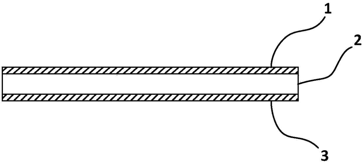
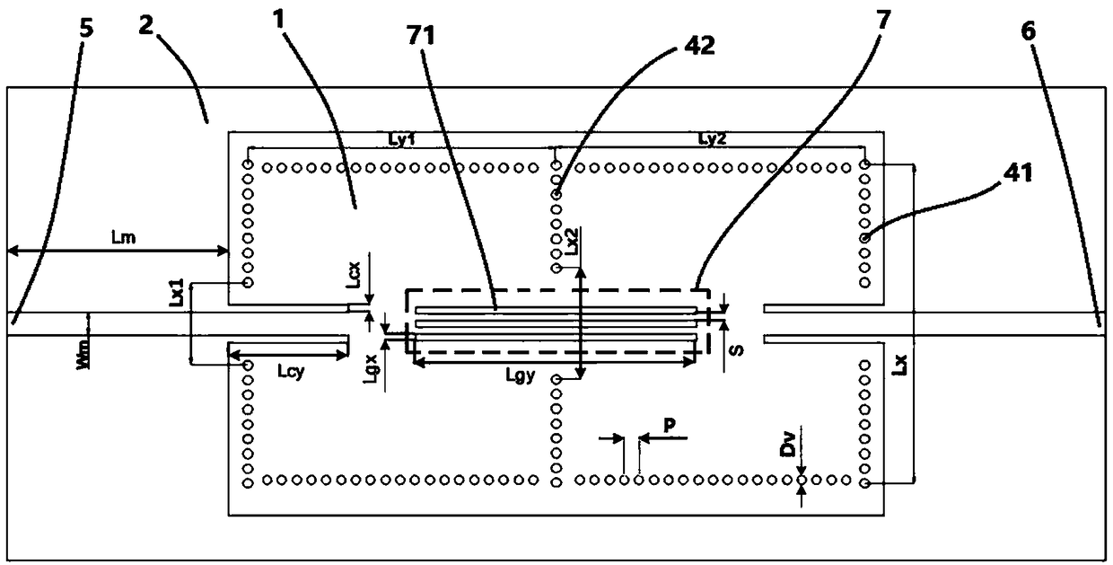
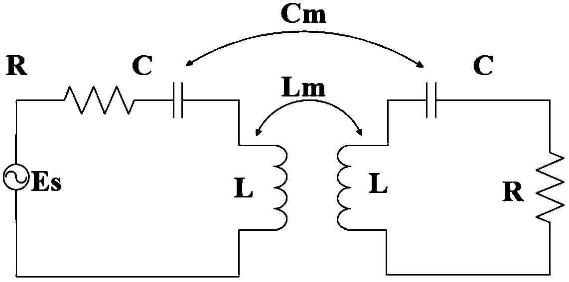
Image
Click on the blue label to locate the original text in one second.
Reading with bidirectional positioning of images and text.
Examples
Embodiment 1
[0046] figure 2 The size of each parameter in is: Wm=1.534mm, Lm=15mm, Lx1=2.8mm, Lx2=7.5mm, Lx3=2.8mm, Lcx=0.51mm, Lcy=8.1mm, Lgx=0.4mm, S=0.8mm , Lgy=18mm, Lx=16.34mm, Ly1=18.25mm, Ly2=18.25mm, D v=0.6mm, P=1mm, the dielectric substrate is Rogers5880, its dielectric constant is 2.2, the loss tangent is 0.0009, and the thickness is 0.508mm.
Embodiment 2
[0048] figure 2 The size of each parameter in is: Wm=1.534mm, Lm=15mm, Lx1=2.8mm, Lx2=7.5mm, Lx3=2.8mm, Lcx=0.51mm, Lcy=8.1mm, Lgx=0.43mm, S=0.86mm , Lgy=18mm, Lx=16.34mm, Ly1=18.25mm, Ly2=18.25mm, D v =0.6mm, P=1mm, the dielectric substrate is Rogers5880, its dielectric constant is 2.2, the loss tangent is 0.0009, and the thickness is 0.508mm.
Embodiment 3
[0050] figure 2 The size of each parameter in is: Wm=1.534mm, Lm=15mm, Lx1=2.8mm, Lx2=7.5mm, Lx3=2.8mm, Lcx=0.51mm, Lcy=8.1mm, Lgx=0.45mm, S=0.9mm , Lgy=18mm, Lx=16.34mm, Ly1=18.25mm, Ly2=18.25mm, D v =0.6mm, P=1mm, the dielectric substrate is Rogers5880, its dielectric constant is 2.2, the loss tangent is 0.0009, and the thickness is 0.508mm.
PUM
Abstract
The invention discloses a substrate integrated waveguide filter with the characteristic of controllable hybrid electromagnetic coupling. The substrate integrated waveguide filter comprises a substrate integrated waveguide resonance cavity. The substrate integrated waveguide resonance cavity consists of a dielectric substrate, two metal layers arranged at the front side and the back side of the dielectric substrate, and peripheral metallic through holes that are formed along the edges of the dielectric substrate and penetrate the two metal layers. An input port and an output port are arranged at the two ends of the substrate integrated waveguide. A plurality of internal metallic through hole groups are formed in the area encircled by the peripheral metallic through holes and include internal metallic through holes that are arranged at two columns in a collinear mode; a sensitive window is formed between the two columns of the internal metallic through holes. A non-resonant node structure arranged above the sensitive window is arranged on the upper metal layer. According to the invention, the electric coupling strength is controlled by adjusting the non-resonant node structure and the magnetic coupling strength is controlled by adjusting the width of the sensitive window, so that whether the transmission zero point is arranged on an upper stop band or a lower stop band can be controlled.
Description
technical field [0001] The invention relates to a substrate integrated waveguide filter, in particular to a controllable hybrid electromagnetic coupling substrate integrated waveguide filter. Background technique [0002] Substrate-integrated waveguide is a new type of waveguide structure that can be integrated in a dielectric substrate that has appeared in the field of microwave and millimeter waves in recent years. The filter formed by it has the advantages of small insertion loss, low radiation, and high power capacity. [0003] In the prior art, a substrate-integrated waveguide filter capable of generating hybrid electromagnetic coupling is proposed, but it cannot realize the controllability of electromagnetic coupling, that is, it is impossible to control the transmission zero point to be located in the upper stop band by controlling the strength of electrical coupling and magnetic coupling. Or the lower stop band, the design flexibility is poor. Contents of the inven...
Claims
Application Information
Patent Timeline
Application Date:The date an application was filed.
Publication Date:The date a patent or application was officially published.
First Publication Date:The earliest publication date of a patent with the same application number.
Issue Date:Publication date of the patent grant document.
PCT Entry Date:The Entry date of PCT National Phase.
Estimated Expiry Date:The statutory expiry date of a patent right according to the Patent Law, and it is the longest term of protection that the patent right can achieve without the termination of the patent right due to other reasons(Term extension factor has been taken into account ).
Invalid Date:Actual expiry date is based on effective date or publication date of legal transaction data of invalid patent.