Long-time iodine flow supply device

A supply device and long-term technology, which is applied to laser parts, electrical components, lasers, etc., can solve the problems of iodine vapor flow rate drop, slow conduction efficiency, and iodine vapor drop

Active Publication Date: 2016-07-13
DALIAN INST OF CHEM PHYSICS CHINESE ACAD OF SCI
View PDF8 Cites 7 Cited by
  • Summary
  • Abstract
  • Description
  • Claims
  • Application Information

AI Technical Summary

Problems solved by technology

[0004] The disadvantage of the iodine vapor supply device of this electric heating evaporation method is that the iodine vapor gradually decreases during the supply process, resulting in a gradual decrease in the flow rate of the iodine vapor
The reason is that the stainless steel heating tube is placed in the iodine liquid and the conduction efficiency is slow, which cannot meet the continuous evaporation of the iodine liquid.

Method used


Image

  • Long-time iodine flow supply device

Examples


Embodiment Construction

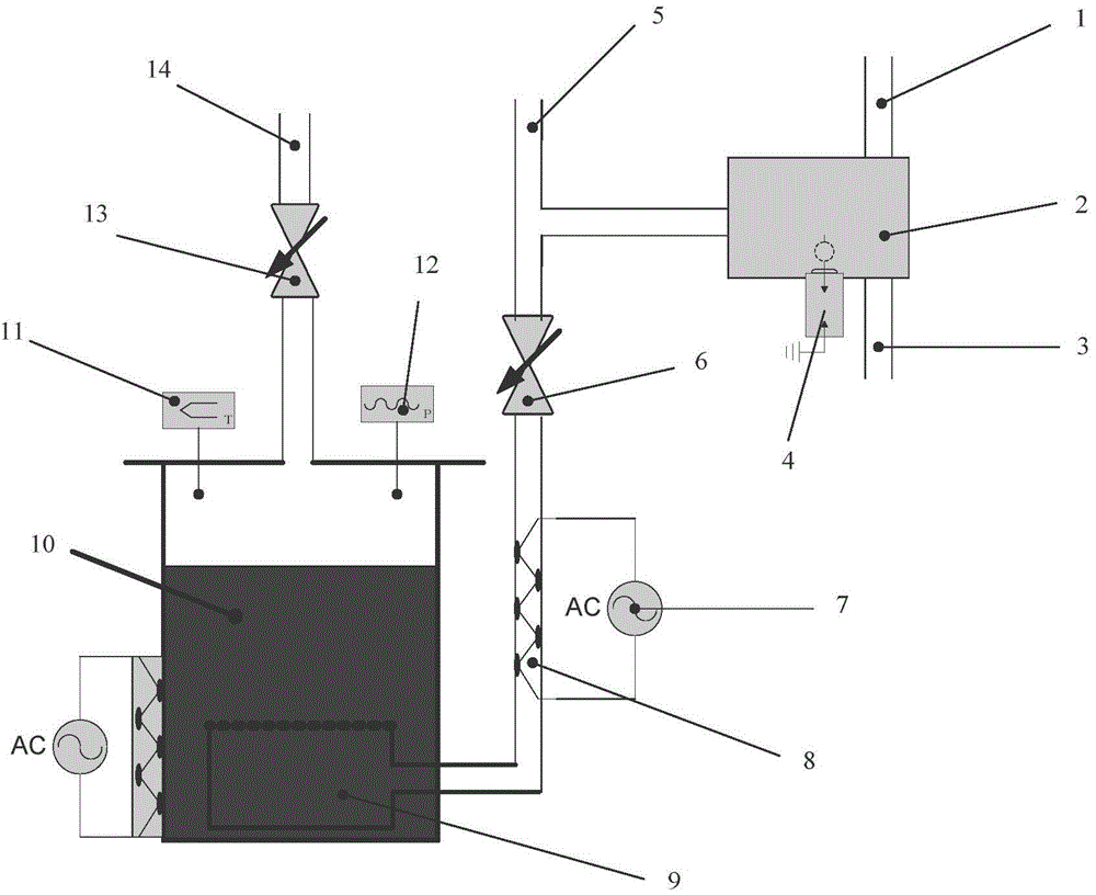
[0010] Such as figure 1 As shown, the cavity 2 and the tank body 10 are respectively the combustion chamber and the fluid storage tank for the material iodine. The combustion chamber is made of stainless steel and cannot leak air at high pressure. The periphery of the combustion chamber is the intake lines 2 and 3 for oxygen and carbon monoxide. A spark plug 4 for ignition is connected to the outer wall of the combustion chamber. Pipeline 5 is used to add diluent gas such as helium or nitrogen to adjust the gas temperature. After the high-temperature carbon dioxide gas flows out from the combustion chamber, it mixes with the low-temperature helium gas, flows through the pneumatic valve 6 and enters the gas distributor 9 . The connecting pipeline between the pneumatic valve and the gas distributor is heated by a temperature-controlled power supply 7 and a heating belt 8, so that its temperature is the same as or slightly higher than the stable temperature in the tank. The t...


PUM


Abstract

The invention provides a long-time iodine flow supply device, and relates to the technology of gas supply of a continuous wave oxygen-iodine chemical laser. The main body of the device has two parts: an electric heating iodine vapor storage tank and a combustion chamber for the combustion of two types of gas. The electric heating iodine vapor storage tank enables solid iodine to be heated to a certain temperature and enables the solid iodine to be changed into liquid iodine. Moreover, there is iodine vapor with a certain saturated vapor pressure on the liquid level. The combustion chamber is a closed space which is used for the combustion of carbon monoxide and oxygen, and the generated high-temperature and high-pressure gas enters the iodine vapor storage tank after the temperature adjustment through diluent gas. High-temperature carbon dioxide gas enters the liquid phase of the iodine vapor storage tank and then forms bubbles, thereby enabling heat energy to be transferred to the liquid iodine and enabling the iodine to be vapored into iodine vapor, wherein the bubbles comprise iodine vapor with a certain density. When the bubbles continue to rise in the liquid phase, the phenomenon of mass and heat transfer continues to happen till the balance is reached. The bubbles flow out from the liquid phase, enter a gas phase, pass through a gas supply pipe and then enter a laser main body.

Description

technical field [0001] The present invention relates to the supply of materials for oxygen iodine chemical lasers. technical background: [0002] Iodine vapor is one of the necessary materials for continuous wave oxygen-iodine chemical lasers. The method of its generation determines the stability, volume and continuity of the iodine vapor flow. The method of production is mainly physical evaporation method, but also chemical method. [0003] The physical evaporation method is to heat the solid iodine into a liquid at high temperature, and control the saturated vapor pressure of the iodine vapor on the surface of the liquid by adjusting the temperature of the iodine liquid. When the air release valve of the closed container is opened, the iodine vapor can flow out into the gas supply pipeline. The specific realization is that the iodine crystal is placed in a vacuum-tight heatable stainless steel tank, and the tank is equipped with accessories such as temperature measurement...

Claims


Application Information

Patent Timeline
Patent Type & Authority Applications(China)
IPC IPC(8): H01S3/036
Inventor 李国富多丽萍金玉奇王元虎于海军汪健曹靖李留成唐书凯王增强康元福
Owner DALIAN INST OF CHEM PHYSICS CHINESE ACAD OF SCI
Why Eureka
Try Eureka