Optical lens die casting device

A technology of optical lenses and switching devices, which is applied to optical components, other household appliances, household appliances, etc., can solve the problems of long pressing station time, slow transfer speed, personal injury accidents, etc., and achieves shortened molding pressing time and high production efficiency The effect of improving and good optical performance

Inactive Publication Date: 2016-07-20
韩金桥
View PDF4 Cites 4 Cited by
  • Summary
  • Abstract
  • Description
  • Claims
  • Application Information

AI Technical Summary

Problems solved by technology

Its main manifestations: 1) Most of the raw materials are cut first, heated to a molten state, and then transferred to the pressing mold for pressing. Not only is cutting time-consuming and labor-intensive, but also the transfer is carried out manually with special clamps. , not easy to operate, slow transfer speed, and low safety factor, resulting in low production efficiency and prone to personal injury accidents; 2) After the lens is pressed and formed, it needs to cool down with the mold before it can be molded, and it takes a long time to occupy the pressing station. In order to shorten the cooling time, the forced rapid cooling method of high-pressure air is often used at present. This cooling method has a great impact on the internal lattice structure of the lens, resulting in a decrease in the optical performance of the lens; 3) In the process of continuous pressing, the indenter and liquid The temperature of the piston rod of the cylinder rises, sometimes even close to the temperature of the molten billet, causing the piston rod to expand, the strength to decrease, deformation, locking, etc., which affect the service life of the liquid cylinder, high failure rate, and also affect the production efficiency of die casting due to frequent maintenance
Problems such as the above have not yet been satisfactorily resolved

Method used


Image

  • Optical lens die casting device
  • Optical lens die casting device
  • Optical lens die casting device

Examples


Embodiment 1

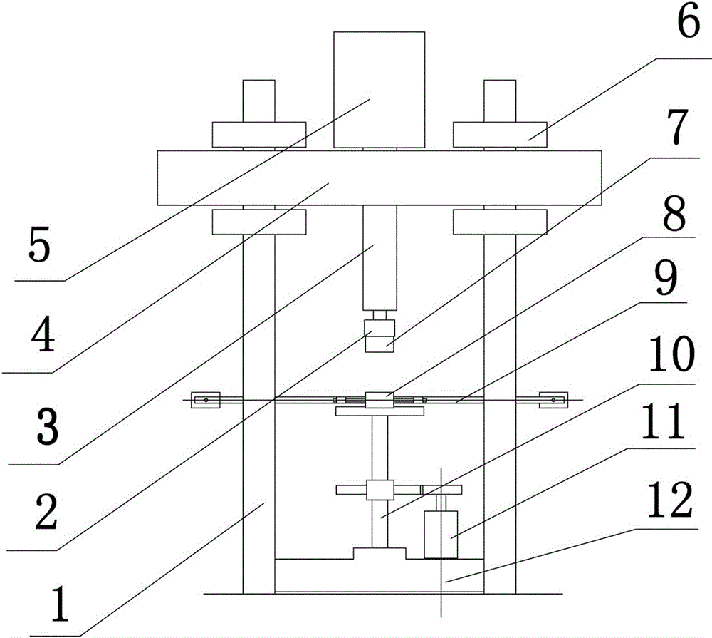
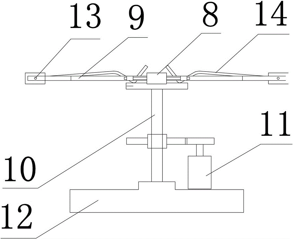
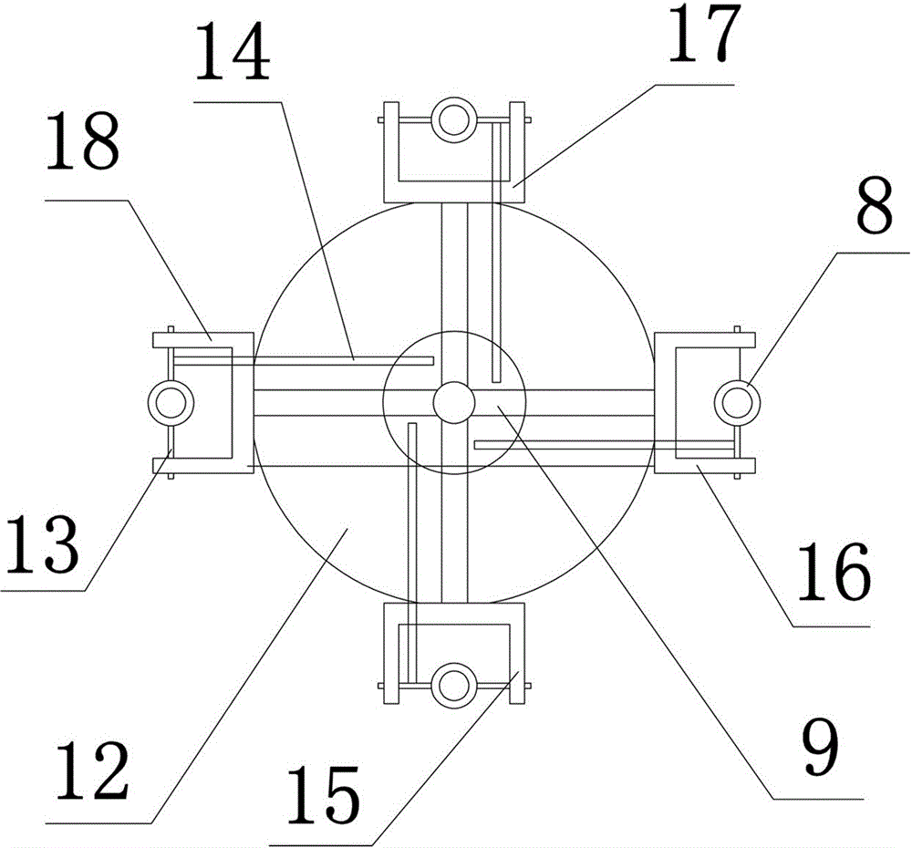
[0026] Such as figure 1 , figure 2 , image 3 As shown, the optical lens die-casting device of the present invention includes a press, a die-casting mold and a multi-station switching device. Wherein, the press machine includes a guide column 1, a beam 4 and a pressure head 2, a pressure hydraulic cylinder 5 is installed on the top of the beam 4, and the pressure head 2 is installed and connected with the piston rod 3 of the pressure fluid cylinder 5. The die-casting mold is composed of an upper die 7 and a plurality of lower dies 8, the upper die 7 is connected to the lower end of the press head 2, and the lower dies 8 are respectively installed on each station of the multi-station switching device. The multi-station switching device includes a base 12 and a mold bracket 9, the mold bracket 9 is connected to the base 12 through a central shaft 10 and a bearing, and the central shaft 10 is connected to a servo motor 11 through a transmission part to drive the central shaft ...

Embodiment 2

[0029] combine figure 2 , image 3 see Figure 4 , this embodiment is a further improvement on the basis of the technical solution of Embodiment 1. In order to further improve the quality of lens die-casting, prevent damage to the mold bracket 9 and prolong its service life, a mold support structure can be provided under the die-casting station 15, The mold support mechanism has a support 19, and a spacer 21 is arranged on the top of the support 19. The height of the top surface of the spacer 21 should be basically equal to the bottom end surface of the lower mold 8, so as to ensure that the lower mold 8 rotates with the mold bracket 9 freedom, and the gap should not be too large. Also can install a telescopic liquid cylinder 22 by connecting support plate 20 on bearing 19, its telescoping end is connected with spacer 21, and spacer 21 is delivered to the below of counterdie after counterdie 8 rotates in place again.

Embodiment 3

[0031] combine figure 2 , image 3 see Figure 5, as a further improvement, the optical lens die-casting device of the present embodiment is provided with a cutting mechanism on the side of the die-casting station 15, which includes upper and lower cutters 24, 25 corresponding to each other, and the upper and lower cutters 24, 25 are respectively connected with compressed fluid Cylinder I, II 23, 26. The cutting mechanism can also be set in combination with the mold support mechanism. The compression cylinder I 23 of the upper cutter 24 can be fixedly connected to the top of the support 19 in the mold support mechanism through the bracket 27, and the compression cylinder II 26 of the lower cutter 25 can be installed on the mold support mechanism. The bottom of the support 19 platens. The positions of the upper and lower cutters 24 and 25 should be as close as possible to the die-casting mold, so as to save the raw material consumption of the lens and reduce the workload of...


PUM


Abstract

The invention discloses an optical lens die casting device. The optical lens die casting device comprises a press, a die casting mold and a multi-station switching device; the die casting mold consists of an upper mold and multiple lower molds; the upper mold is connected to the lower end of a pressing head of the press; and the lower molds are respectively mounted on all stations of the multi-station switching device. The multi-station switching device includes a base and a mold bracket; the mold bracket is rotationally connected with the base through a center shaft, and is provided with multiple die casting stations, cooling stations and mold rising stations capable of being switched; the die casting stations, the cooling stations and the mold rising stations are respectively connected to the lower molds through rotating shafts; and the center shaft is connected with a servo motor through a transmission part. The device performs the die casting for optical lenses; and the lenses, molded through hot pressing, timely rotate away from the die casting stations to reach the cooling stations for naturally cooling to form better internal lattice structures, so that the better optical performance of the optical lenses can be guaranteed, the quality is greatly improved, the molding pressing time is largely shortened, and the production efficiency can be improved by 5-10 times.

Description

technical field [0001] The invention relates to the technical field of workpiece detection, in particular to an optical lens die-casting device. Background technique [0002] With the wide use of optical equipment and instruments in various fields of society, the demand for optical lenses is increasing rapidly. As the first process of optical lens processing, the die-casting of lens blanks mostly follows the traditional pressing method, namely Press one by one on the press with a forming die, although various automatic control measures have been adopted at present, there are still many problems and defects. Its main manifestations: 1) Most of the raw materials are cut first, heated to a molten state, and then transferred to the pressing mold for pressing. Not only is the cutting time-consuming and labor-intensive, but also the transfer is carried out manually with special clamps. , not easy to operate, slow transfer speed, low safety factor, resulting in low production effi...

Claims


Application Information

Patent Timeline
Patent Type & Authority Applications(China)
IPC IPC(8): B29C43/08B29C43/32B29C43/40B29C43/52B29L11/00
CPCB29C43/08B29C43/32B29C43/40B29C43/52B29C2043/403B29L2011/0016
Inventor 韩金桥韩丰斐
Owner 韩金桥
Why Eureka
Try Eureka