Coil system for electromagnetic wave propagation resistivity log

A technology of resistivity logging and coil system, which is used in electromagnetic wave detection, electrical/magnetic detection for logging records, wellbore/well components, etc., and can solve problems such as signal attenuation of receiving coils

Active Publication Date: 2016-07-20
INST OF ELECTRICAL ENG CHINESE ACAD OF SCI
View PDF7 Cites 3 Cited by
  • Summary
  • Abstract
  • Description
  • Claims
  • Application Information

AI Technical Summary

Problems solved by technology

[0008] In order to overcome the problem of serious attenuation of the receiving coil signal caused by increasing the source distance, the present invention proposes an electromagnetic wave resistivity logging coil system

Method used


Image

  • Coil system for electromagnetic wave propagation resistivity log
  • Coil system for electromagnetic wave propagation resistivity log
  • Coil system for electromagnetic wave propagation resistivity log

Examples


Embodiment Construction

[0019] Combine below Attached picture The present invention will be further described with specific embodiments.

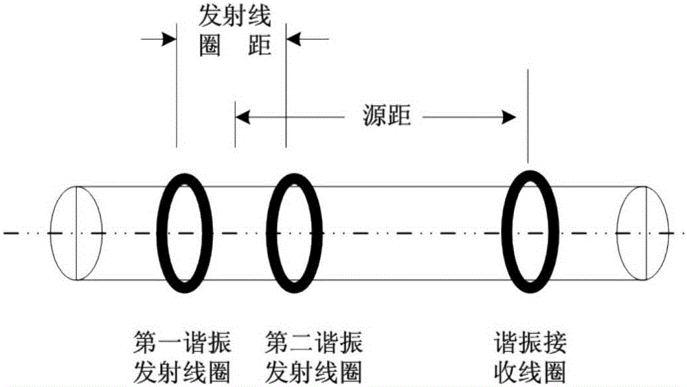
[0020] Such as figure 1 As shown, the electromagnetic wave resistivity logging coil system of the present invention includes the first resonant transmitting coil T 1 , the second resonant transmitting coil T 2 and resonant receiving coil R. Both the resonant transmitting coil and the resonant receiving coil are independent Loop, no direct physical connection. The distance between the resonant receiving coil R and the centers of the two resonant transmitting coils is the source distance, and the first resonant transmitting coil T 1 and the second resonant transmit coil T 2 The distance between them is the transmitter coil pitch.

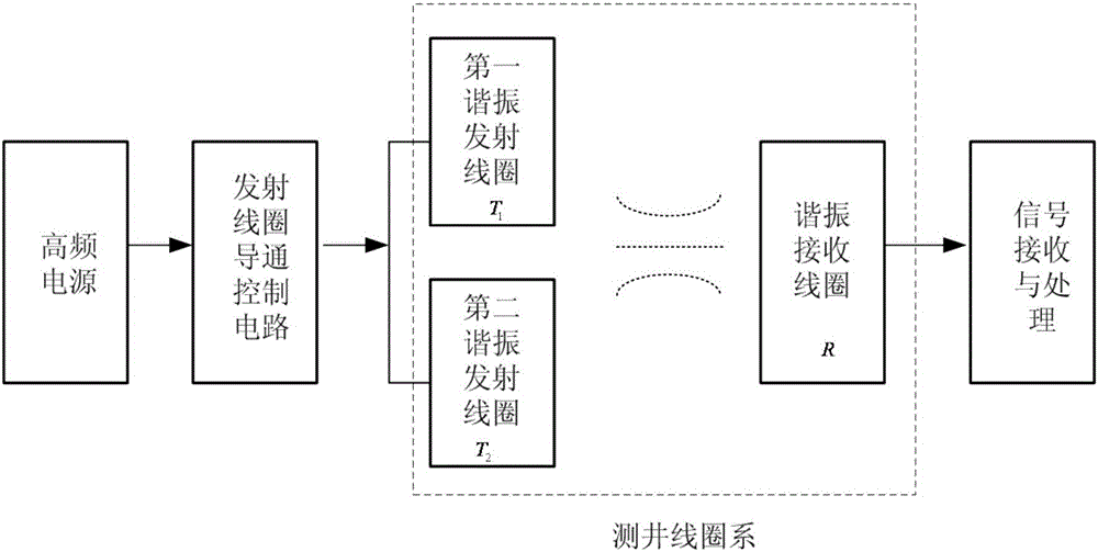
[0021] The resonant transmitting coil, the resonant receiving coil and the external connection circuit of the electromagnetic wave resistivity logging coil system of the present invention Such as figure 2 shown. The loggin...


PUM


Abstract

The invention relates to a coil system for electromagnetic wave propagation resistivity log. The coil system consists of two resonant transmitting coils and a resonant receiving coil, wherein the resonant transmitting coils are connected with a high frequency power source through a conducting control circuit, the resonant transmitting coils and the resonant receiving coil are free from direct physical connection, and the resonant receiving coil is connected with a signal receiving and processing circuit. Each of the resonant transmitting coils is formed by connection of multi-turn coils and a matching capacitor, the resonant receiving coil is formed by connection of multi-turn coils and a matching capacitor, and besides, the resonant frequency of the resonant transmitting coils is the same as that of the resonant receiving coil. At the same measuring point, the two resonant transmitting coils are sequentially connected with the high frequency power source in a conducting manner, and the voltage amplitude and the phase of two ends of the same resonant receiving coil are separately measured.

Description

technical field [0001] The invention relates to a coil system for electromagnetic wave resistivity logging. Background technique [0002] Electrical logging uses electromagnetic field analysis and measurement to study the characteristics of the electrical conductivity or dielectric constant of the formation section around the wellbore to evaluate the formation. Electromagnetic wave resistivity logging is a commonly used alternating current logging method, the frequency is generally between 100kHz-4MHz, and the formation resistivity and permittivity information is obtained by measuring the amplitude and phase attenuation of the receiving coil to evaluate the reservoir condition . [0003] As the development of oil and gas resources enters the middle and later stages, the proportion of highly deviated wells, horizontal wells and multilateral wells is increasing. The traditional wireline logging method measures the parameters around the well after the drilling is completed, a...

Claims


Application Information

Patent Timeline
Patent Type & Authority Applications(China)
IPC IPC(8): E21B49/00G01V3/30
CPCE21B49/00G01V3/30
Inventor 张超刘国强夏正武李艳红李士强刘宇
Owner INST OF ELECTRICAL ENG CHINESE ACAD OF SCI
Why Eureka
Try Eureka