
rotary piston engine

A technology of rotary piston and engine, applied in the direction of internal combustion piston engine, combustion engine, machine/engine, etc., can solve the problems of many vulnerable parts, low mechanical efficiency and high manufacturing cost, achieve low vibration and noise, and save production costs , the effect of high mechanical efficiency

Active Publication Date: 2018-06-05
贺坤山
View PDF7 Cites 0 Cited by
  • Summary
  • Abstract
  • Description
  • Claims
  • Application Information

AI Technical Summary

Problems solved by technology

It is a cylinder whose inner wall is composed of arc-shaped lines, and the rotor and N blades which are uniformly arranged in the rotor channel and have a corresponding diameter of the arc top surface surround it; the fixed rotation centers of the rotor and blades are offset ; The rotor drives the blades to rotate at the same speed but not concentrically, and the blades, rotors, and stators have a corresponding connection structure that can meet the required relative motion and ensure the required sealing; after the corresponding prototype test run and further analysis and research show that , the common problems of the first two patents are that the structural features of the invention can not effectively solve the sealing problem. The sealing parts are mutual contact or partial overlapping dispersions, which cannot form a continuous integral sealing part. The sealing effect is not good, and the sealing structure Relatively complicated, which hinders the promotion of patents
The existing reciprocating piston engine with volumetric crank-link mechanism has many disadvantages such as bulky, complex mechanism, high manufacturing cost, many vulnerable parts, and low mechanical efficiency.

Method used


Image

  • rotary piston engine
  • rotary piston engine
  • rotary piston engine

Examples


Embodiment Construction

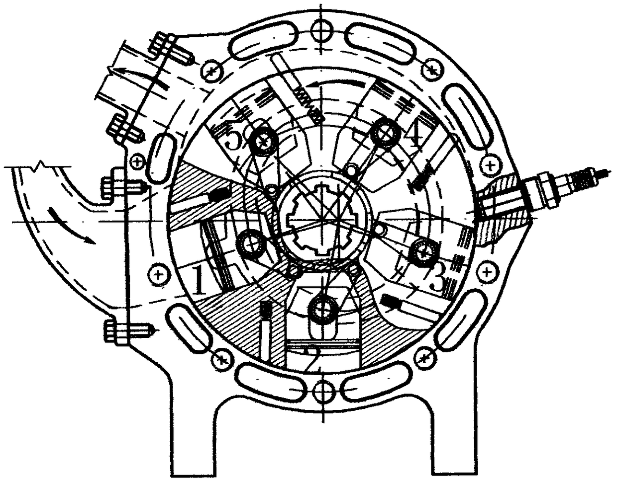
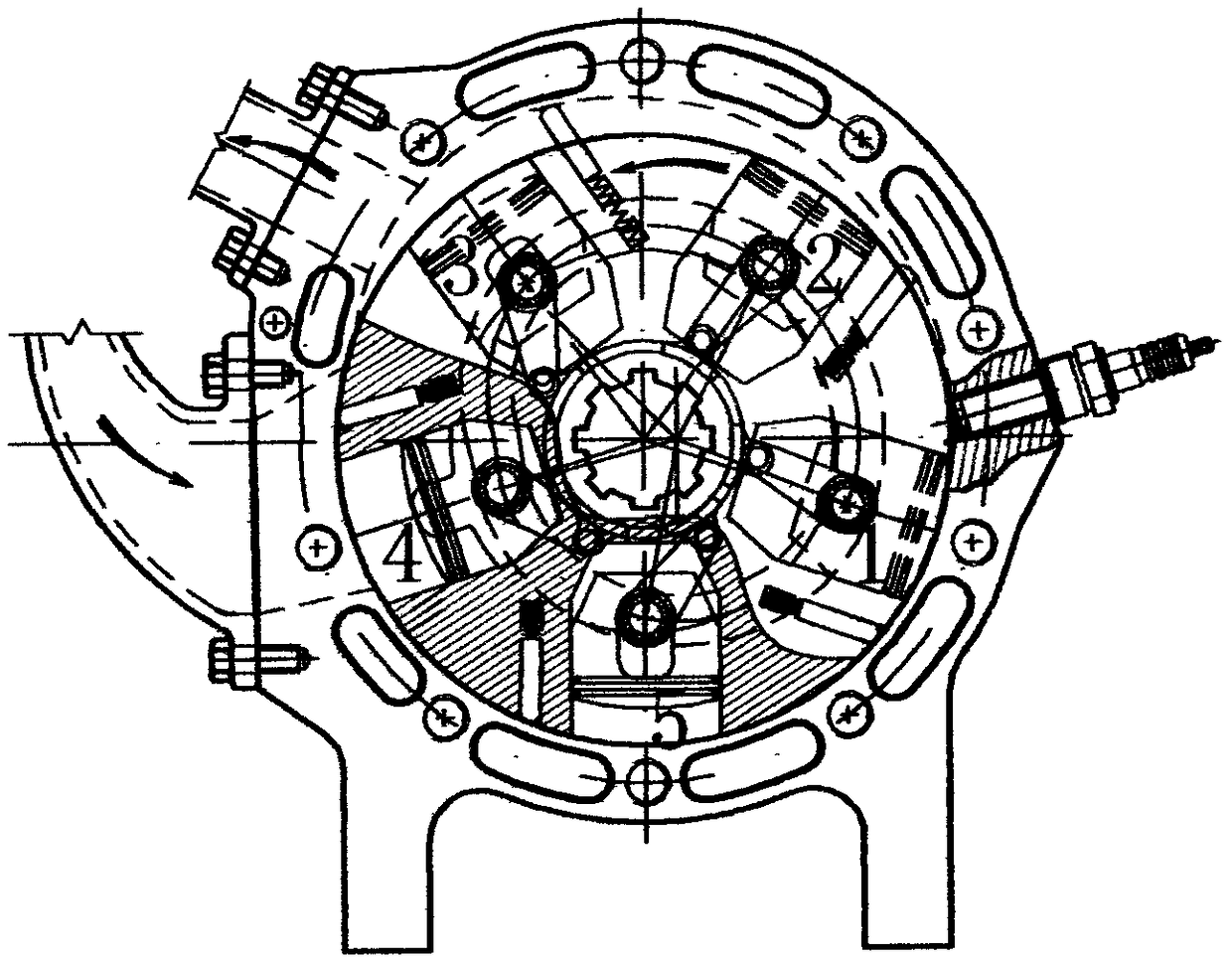
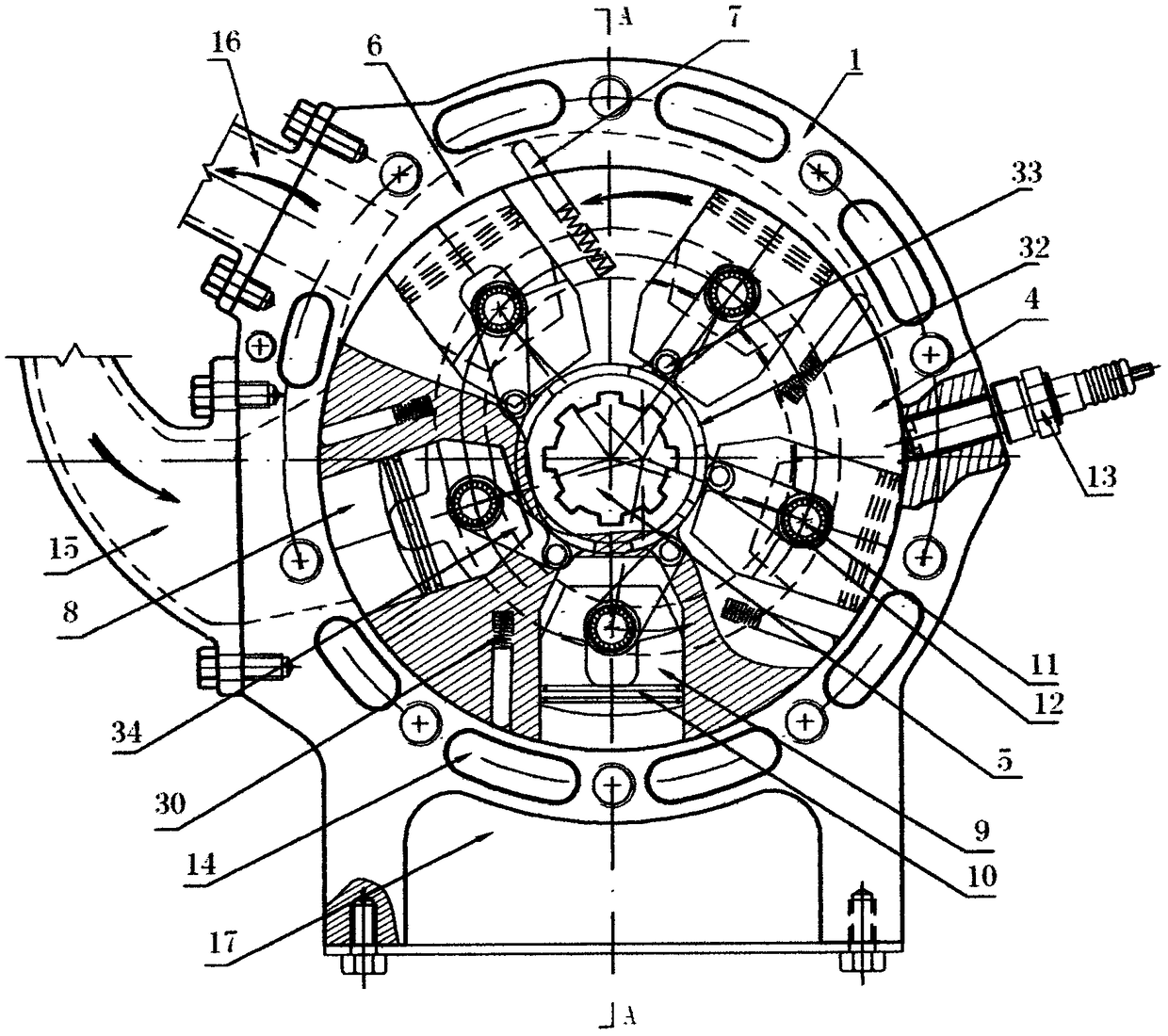
[0027]With reference to above-mentioned accompanying drawing, a kind of rotary piston engine comprises cylinder body 1, front and rear end cover 2,3 synthetic housing; Proper position on cylinder body is respectively provided with intake and exhaust channel 15,16, spark plug 13, cooling cycle Waterway 14 and oil tank 17, the cooling circulation waterway 14 is provided with inlet 27 and outlet 28; rear end cover 3 is equipped with oil pump 21, driven gear shaft 22, driven gear 24 and rear end cover main bearing 25, front end cover 2 The main bearing 26 of the front end cover is installed, and the front end cover 2 is provided with a cooling circulation channel rotor 4 and a driving gear 23 mounted on the engine main shaft 5; it is characterized in that there are no N pistons 9 and N piston pins 11 in the rotary piston engine The two ends of the piston pin are fitted with a connecting rod 34, the other end of which is connected to the thrust head 33, and the thrust head 33 is pre...


PUM


Abstract

The invention relates to a rotating piston engine. The rotating piston engine comprises a shell consisting of a cylinder 1 and front and back end covers 2 and 3; a rotor 4 is mounted on a main shaft 5; the main shaft is mounted in main bearings of the front and back end covers; N cylinder chambers 8 are uniformly distributed on the rotor 4; N pistons 9 are embedded; two ends of piston pins 11 extend into piston pin moving rails 18 arranged on the front and back end covers to perform a same-speed misaligned rotating motion along with the rotor; the outer diameter of the rotor 4 and the inner diameter of the cylinder 1 are cylinders with the same diameter, and are in clearance sliding contact; a reciprocating crankshaft type internal combustion engine piston air sealing structure is adopted to solve the problem of difficult air sealing of a rotor engine; meanwhile, the principles of front-grade continuous air compression of a gas turbine and continuous acting of high-pressure gas in a combustion chamber are acted in the rotating piston engine; the rotating piston engine overcomes multiple defects in a traditional internal combustion engine technology; and the rotating piston engine has the excellent effects of simple structure, high mechanical efficiency, stable operation, no vibration and low noise.

Description

Technical field: [0001] The invention relates to a rotary piston engine, which belongs to the field of internal combustion engines. Background technique: [0002] The principle of the reciprocating piston internal combustion engine of the existing volumetric crank-link mechanism is to rely on the periodic change of the volume of the sealed working chamber to increase the pressure of the mixed combustible gas (or compressed gas), and then the ignition system (or fuel injection system) Fuel injection) ignites the expansion work to push the crank connecting rod mechanism to realize the engine that can work reciprocatingly by itself; the method to realize its principle is that the starter drives the crankshaft to rotate, the connecting rod links the crankshaft and the piston, and the reciprocating cycle changes in the cylinder. After the deflagration of the high-pressure combustible medium, the expansion work pushes the crank connecting rod mechanism to realize the reciprocating...

Claims


Application Information

Patent Timeline
Patent Type & Authority Patents(China)
IPC IPC(8): F02B55/00F02B55/02F02B55/10F02B55/08
CPCF02B55/00F02B55/02F02B55/08F02B55/10
Inventor 贺坤山
Owner 贺坤山
Learn More