
Valve with filtering function

A valve and function technology, applied in the direction of filtration separation, sliding valve, valve device, etc., can solve the problems of short service life, easy valve blockage, increased operation, etc., to achieve uniform utilization and loss, improve filtration efficiency, and reduce cleaning costs. Effect

Inactive Publication Date: 2016-07-20
潘豪杰
View PDF8 Cites 3 Cited by
  • Summary
  • Abstract
  • Description
  • Claims
  • Application Information

AI Technical Summary

Problems solved by technology

[0002] At present, there are mainly two types of valves on water meters used by people. One is a ball valve type valve. This valve controls the size of the water flow by adjusting the gap between the ball and the outlet of the channel. The valve has poor sealing performance and short service life. And it is prone to water leakage. In addition, this kind of valve cannot make the water meter realize automatic control, which increases the trouble in operation.
Another type of valve is called pilot valve, which is often called a diaphragm valve. This valve controls the water flow by putting a cylindrical diaphragm on the tapered plug and adjusting the gap between the diaphragm and the outlet of the channel. The valve is prone to blockage, and the diaphragm often cannot be used normally due to wear or crushing. People need to replace the diaphragm frequently, which is very inconvenient to use.
[0003] Moreover, the valves on the existing water meters do not have a filtering function, and the valve cores are easily damaged

Method used


Image

  • Valve with filtering function
  • Valve with filtering function
  • Valve with filtering function

Examples


Embodiment Construction

[0021] The present invention will be described in further detail below in conjunction with the accompanying drawings.

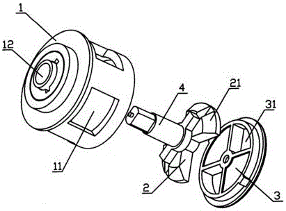
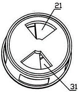
[0022] Such as figure 1 and 2 , the inner cavity of the shell 1 of the valve with filtering function is cylindrical, and four water inlets 11 are distributed on the side wall of the shell 1, and the water volume control mechanism is located at the end of the inner cavity of the shell 1. The water volume control mechanism is mainly composed of a valve stator 3 and a valve rotor 2. The valve stator 3 is installed in cooperation with the annular step at the end of the inner cavity of the casing 1. Two fan-shaped liquid flow ports 31 are symmetrically distributed on both sides of the valve stator 3 axis. One end face of the valve rotor 2 fits with the valve stator 3 and can rotate relative to the valve stator 3. The valve rotor 2 is two blocks 21 distributed symmetrically to its axis. When the flow port 31 is used, the liquid flow port 31 can be blocked to prev...


PUM


Abstract

The invention discloses a valve with a filtering function. The valve comprises a shell, and a water quantity control mechanism positioned in the shell; the water quantity control mechanism includes a valve stator, and a valve rotor capable of rotating on the valve stator relative to the valve stator; the valve stator has at least one liquid flowing-in port; the valve rotor has stoppers for opening the liquid flowing-in ports in part phase when rotating on the valve stator; in other phases, the stoppers shield the liquid flowing-in ports; two liquid flowing-in ports of the valve stator are provided, and are symmetrically distributed on two sides of the center of the valve stator; two stoppers on the valve rotor are provided, and the positions thereof on the valve rotor are corresponding to the liquid flowing-in ports of the valve stator; and the liquid flowing-in ports of the valve stator are connected with filter pipes. The valve has the advantages of simple structure, long service life, excellent tightness, capability of realizing filtration and easy realization of automatic control.

Description

technical field [0001] The invention relates to a valve, in particular to a valve with filtering function used on a water meter. Background technique [0002] At present, there are mainly two types of valves on water meters used by people. One is a ball valve type valve. This valve controls the size of the water flow by adjusting the gap between the ball and the outlet of the channel. The valve has poor sealing performance and short service life. And the phenomenon of water leakage is prone to occur. In addition, this valve cannot make the water meter realize automatic control, thereby increasing troubles in operation. Another type of valve is called pilot valve, which is often called a diaphragm valve. This valve controls the water flow by putting a cylindrical diaphragm on the tapered plug and adjusting the gap between the diaphragm and the outlet of the channel. The valve is prone to blockage, and the diaphragm often cannot be used normally due to wear or crushing. Peopl...

Claims


Application Information

Patent Timeline
Patent Type & Authority Applications(China)
IPC IPC(8): F16K3/04B01D35/02
CPCF16K3/04B01D35/02F16K3/0209
Inventor 潘豪杰
Owner 潘豪杰
Learn More