Hot air type penetration reverse flow fluidization drying machine with tail heat utilization and inertial dust collecting functions

A fluidized drying and inertial technology, applied in progressive dryers, heating to dry solid materials, dryers, etc., can solve problems such as difficulty in disassembly, prevent fatigue fractures, facilitate lightweight, and enhance axial elasticity Effect

Inactive Publication Date: 2016-07-20
罗军
View PDF6 Cites 18 Cited by
  • Summary
  • Abstract
  • Description
  • Claims
  • Application Information

AI Technical Summary

Problems solved by technology

In the actual assembly of shafts and holes with transmission threads, in order to achieve large load-bearing functions, the size of the threaded shafts and matching nut-like components are relatively large, and it is often easy and convenient to screw in during assembly, and It can rea

Method used


Image

  • Hot air type penetration reverse flow fluidization drying machine with tail heat utilization and inertial dust collecting functions
  • Hot air type penetration reverse flow fluidization drying machine with tail heat utilization and inertial dust collecting functions
  • Hot air type penetration reverse flow fluidization drying machine with tail heat utilization and inertial dust collecting functions

Examples


Example Embodiment

[0035] The present invention will be further described in detail with reference to the accompanying drawings.

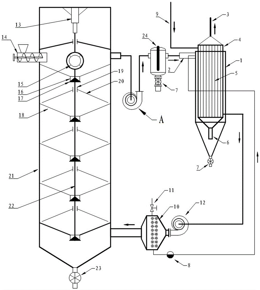
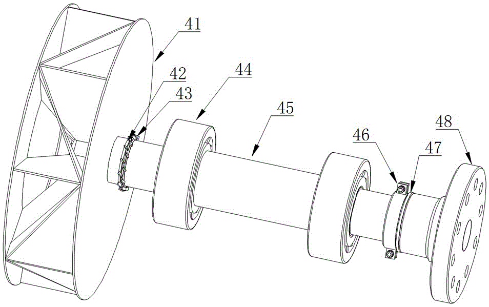
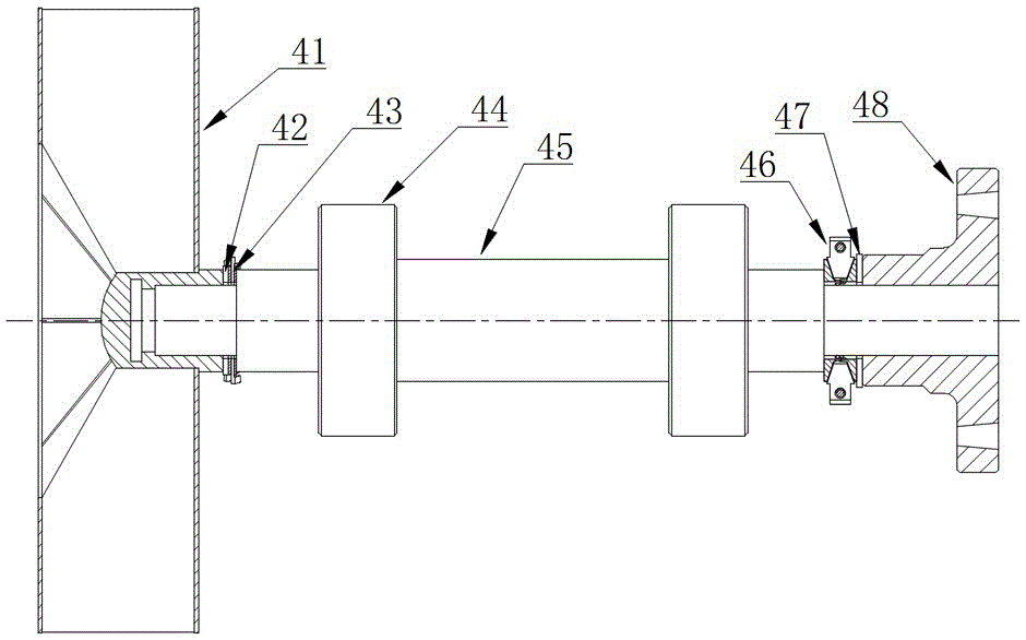
[0036] Such as figure 1 , figure 2 , image 3 , Figure 4 , Figure 5 , Image 6 , Figure 7 , Figure 8 with Picture 9 The tail heat shown uses inertial dust-catching hot air penetrating countercurrent fluidized dryer, including drying tower 21 and induced draft fan A. The upper part of drying tower A is equipped with a material seal screw feeder 14, and the bottom is equipped with a closed air discharger 23 ; The upper part of the drying tower is connected to the induced draft fan A, and the induced draft fan A is tangentially connected to the high-efficiency cyclone dust removal tail heat recovery device formed by the superposition of the tubular heat exchanger 4 and the cyclone dust collector 1 through the inertial dust catcher 24 and then drains; The inlet end of the shell side of the tubular heat exchanger 4 is connected to the atmosphere, and the outlet end is ...


PUM


Abstract

The invention discloses a hot air type penetration reverse flow fluidization drying machine with tail heat utilization and inertial dust collecting functions. The upper portion of a drying tower is connected with an induced draft fan. The induced draft fan is connected with an efficient cyclone dedusting tail heat recovery device in a tangential manner through an inertial dust collecting device and then performs evacuation, wherein the efficient cyclone dedusting tail heat recovery device is formed by overlaying a tube bank type heat exchanger and a cyclone dust collector. The air inlet end of a shell pass of the tube bank type heat exchanger is communicated with atmosphere, and the air outlet end is connected with the lower portion of the drying tower through an air blower and a steam fin heater; and blades of an impeller of the induced draft fan are arranged to be in a radiation shape and are in radial and central symmetry with respect to an impeller shaft, the dust can be cleared up in time through centrifugal force, and safety accidents are avoided. By the adoption of the hot air type penetration reverse flow fluidization drying machine, the drying efficiency is improved, and energy saving and emission reduction are achieved; and more importantly, the disassembly and assembly technology of the induced draft fan is improved greatly, so that pressure applied to the shaft shoulder end face of a screw by components similar to a nut component can be eliminated simply when the induced draft fan is disassembled, and the problem that the induced draft fan is locked continuously and automatically and cannot be disassembled easily under the load action due to threaded assembly is solved effectively; and the hot air type penetration reverse flow fluidization drying machine is especially suitable for convenient and fast disassembly of a large-scale fan which is locked in a threaded manner, and the effect is particularly obvious.

Description

technical field [0001] The invention relates to a drying machine, which specifically refers to a penetrating countercurrent fluidization drying machine which utilizes inertial dust-collecting hot air at the end of the fan without dust accumulation and is easy to disassemble and overhaul. Background technique [0002] Due to its mature technology, strong adaptability, low operating cost and strong reliability, the hot air dryer is still one of the main preferred equipment for drying materials. , and the effective recovery of tail heat is of special significance for improving drying efficiency and realizing energy saving and emission reduction. [0003] The induced draft fan is the key equipment of the hot air dryer. The induced draft fan is generally a centrifugal fan. The continuous, stable and reliable operation of the induced draft fan is very important for the dryer. Since most of the occasions where the dryer is used contain a certain amount of dust, the induced draft fa...

Claims


Application Information

Patent Timeline
IPC IPC(8): F26B15/26F26B25/00F26B21/00F26B3/092F23J15/02F28D7/16
CPCF23J15/027F26B3/092F26B15/26F26B21/00F26B25/005F28D7/16Y02P70/10
Inventor 张旭银永忠张思言
Owner 罗军
Why Eureka
Try Eureka