Highly-reliable main circuit topological structure of railway ground deflector

A converter device and topology technology, applied in the direction of output power conversion device, AC power input conversion to AC power output, electrical components, etc., can solve the problem of low harmonic order, difficult to ensure power device voltage equalization, Advanced problems, achieve reliability advantages, facilitate capacity expansion, and reduce harmonic pollution

Inactive Publication Date: 2016-07-20
中国船舶重工集团公司第七一二研究所 +2
View PDF13 Cites 13 Cited by
  • Summary
  • Abstract
  • Description
  • Claims
  • Application Information

AI Technical Summary

Problems solved by technology

The disadvantages of this topology are: 1) The direct series connection of power devices is difficult to ensure the voltage equalization between power devices. If the driving signal is slightly out of sync, there will be overvoltage breakdown of power devices, which reduces the reliability of this topology; 2. ) Although there are many power devices in series in each bridge arm, the output level of this topology is only 2-level or 3-level. Due to the small number of levels, the harmonic order and high amplitude of the device output to the AC side are low. The AC side itself is a harmonic source, and it is difficult to meet the requirements of the railway system for power quality
The disadvantages of this topology are: 1) Each H-bridge requires an independent DC bus, which cannot be applied to a back-to-back four-quadrant converter system; 2) The H-bridge modules are electrically connected to each other, and when some of the H-bridges fail, the The inverter will not be able to output the rated voltage, and the system reliability is not high

Method used


Image

  • Highly-reliable main circuit topological structure of railway ground deflector
  • Highly-reliable main circuit topological structure of railway ground deflector
  • Highly-reliable main circuit topological structure of railway ground deflector

Examples


Embodiment Construction

[0028] The present invention will be described in further detail below in conjunction with the accompanying drawings.

[0029] The invention can be used in the fields of dynamic reactive power compensation of railway catenary, active filtering of railway catenary, power adjustment of railway traction power supply arm, same-phase power supply of railway traction, uninterrupted power overshoot of railway trains and other fields.

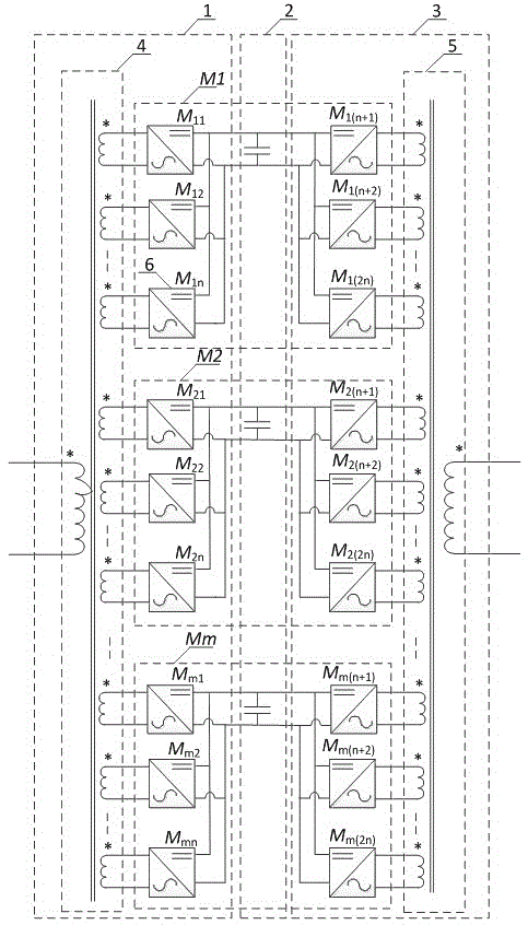
[0030] The proposed converter topology is AC-DC-AC structure, including input multi-winding transformer, output multi-winding transformer, converter subsystem and so on. The proposed converter topology can design m electrically isolated converter subsystems according to the conversion power requirements of the system. The power modules in the converter subsystems are controlled by carrier phase-shift PWM modulation strategies and cascaded through the magnetic field of the isolation transformer. The operation can reduce the harmonic distortion rate of t...


PUM


Abstract

The invention discloses a highly-reliable main circuit topological structure of a railway ground deflector. The highly-reliable main circuit topological structure comprises a rectification unit, an intermediate DC link and an inversion unit, wherein the rectification unit comprises a single-phase input multi-winding isolation transformer and N power modules on the rectification side. The primary side of the single-phase input multi-winding isolation transformer is connected with a railway traction network, and the secondary side of the single-phase input multi-winding isolation transformer is a plurality of electrically isolated multi-winding coils. Each multi-winding coil is connected with the AC input side of a rectification-side power module, the positive DC bus of the power module is in parallel with the positive DC bus of the intermediate DC link, and the negative DC bus of the power module is in parallel with the negative DC bus of the intermediate DC link. M electrical isolation converter sub-systems can be designed according to system power transformation requirements, power modules in the converter sub-systems are controlled through a carrier phase-shift PWM modulation strategy, cascade operation is carried out through the magnetic field of an isolation transformer, and the reliability of a converter is improved.

Description

technical field [0001] The invention belongs to the field of rail transit high-voltage and high-power converter technology, and relates to a high-reliability main circuit topology of a railway ground converter device, which is used for dynamic reactive power compensation of railway catenary, active filtering of railway catenary, and railway traction power supply arm Power regulation, railway traction in-phase power supply, uninterrupted power supply of railway trains, equal high-voltage and large-capacity power electronic conversion fields. Background technique [0002] Electrified railways have played a huge role in the construction and development of the national economy. With the development of market economy and related industries in the electrical field, electrified railway technology has made great progress, and electrified railways are developing towards high speed and high power. my country's railway traction network adopts phase-separated and segmented single-phase ...

Claims


Application Information

Patent Timeline
Patent Type & Authority Applications(China)
IPC IPC(8): H02M5/458H02M1/12
CPCH02M1/12H02M5/4585H02M1/007
Inventor 张新民方华松高晓峰刘君石媛
Owner 中国船舶重工集团公司第七一二研究所
Why Eureka
Try Eureka