Combined piston type electronic vacuum pump for automobile

An electronic vacuum pump and combined piston technology, applied in piston pumps, variable displacement pump components, pumps, etc., can solve the problem of uneven sealing state and stress state of flexible sealing rings, complex structure and assembly, and reduced life and performance of vacuum pumps. problems, to improve assembly safety and flexibility, avoid positioning and press use, increase life and performance

Inactive Publication Date: 2016-07-27
ZHEJIANG ASIA PACIFIC MECHANICAL & ELECTRONICS
View PDF5 Cites 5 Cited by
  • Summary
  • Abstract
  • Description
  • Claims
  • Application Information

AI Technical Summary

Problems solved by technology

However, the motion of the existing piston-type electric vacuum pump is a process in which the eccentric shaft rotates around the rotation center to drive the piston to move. This process will inevitably produce dynamic unbalance and changes in the turbulence of the rotating shaft, resulting in large noise, especially in It is especially obvious during high-speed rotation, and the dynamic balance mechanism is particularly important at this time
However, some piston-type electric vacuum pump dynamic balance mechanisms that consider dynamic balance use interference riveting connections, which require high assembly conditions and difficult assembly, and once the work fails or there is an error in production assembly, the entire product will be scrapped and cannot be carried out. Subsequent maintenance or parts replacement, resulting in the use and production cos

Method used


Image

  • Combined piston type electronic vacuum pump for automobile
  • Combined piston type electronic vacuum pump for automobile
  • Combined piston type electronic vacuum pump for automobile

Examples


Embodiment Construction

[0060] The present invention will be further described below in conjunction with drawings and embodiments.

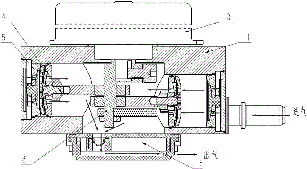
[0061] Such as figure 1 As shown, the present invention includes a valve body 1, a motor assembly installed on the top surface of the valve body 1, a sound-absorbing exhaust assembly 6 installed on the valve body 1, and a combined dynamic balance drive eccentric shaft assembly 3 built into the valve body 1 , two integrated one-way valve combined thin ball piston assembly 4 and two intake one-way valve 5.

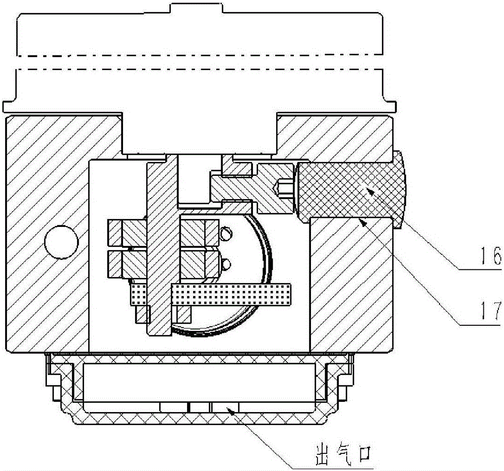
[0062] Such as image 3 As shown, the valve body 1 is machined from aluminum alloy, the valve body 1 is provided with a cylindrical central cavity 14 penetrating to the lower end surface, the upper end surface of the valve body 1 is provided with a motor mounting hole 15, and the left and right end surfaces of the valve body 1 are separated. There are left stepped hole 11 and right stepped hole 12 with the same structure, and the left stepped hole 11, right stepped ...


PUM


Abstract

The invention discloses a combined piston type electronic vacuum pump for an automobile. The combined piston type electronic vacuum pump comprises a valve body, an electric motor assembly, a noise reduction and exhaust assembly, an eccentric shaft assembly, two piston assemblies and two air inlet one-way valves. The valve body is provided with a center inner cavity, a motor mounting hole is formed in the upper end face of the valve body, the valve body is provided with a left ladder hole and a right ladder hole, and the left ladder hole, the right ladder hole and the motor mounting hole are all communicated with the center inner cavity; a combined type dynamic balance transmission eccentric shaft assembly is mounted in the center inner cavity, the center inner cavity is connected with the noise reduction and exhaust assembly for carrying out covering and sealing, and the electric motor assembly is mounted in the motor mounting hole; and the end face of the left ladder hole and the end face of the right ladder hole are connected with end covers for sealing, the piston assemblies and the air inlet one-way valves are arranged in the left ladder hole and the right ladder hole, and the electric motor assembly is mounted on the left ladder hole and the right ladder hole, and is connected with the eccentric shaft assembly to drive the assembly to rotate. A new transmission balance mechanism, a piston structure and the like are adopted in the vacuum pump, the assembly cost and the machining cost are reduced, the assembly safety is improved, sealing of the pump is obviously improved, the noise of the pump is obviously lowered, the service life of the pump is obviously prolonged, and various requirements of automobile use can be met.

Description

technical field [0001] The invention relates to a vacuum pump, in particular to a combined piston-type electronic vacuum pump for automobiles, which belongs to the field of electric automobile servo braking. Background technique [0002] With the rapid development of electric vehicles, electric motors have replaced the internal combustion engines of traditional vehicles. However, the brake booster system of the electric vehicle at the present stage is still based on the traditional brake booster. Without the vacuum source of the internal combustion engine, a vacuum pump is required to provide the vacuum source for the brake booster. Electric vacuum pumps are produced for this purpose. At present, most of the electric vacuum pumps used in vehicles are of vane type, which has a complex structure, requires high machining accuracy, short continuous working time, and high noise. Once the vane fails, it will lead to a series of shortcomings such as direct failure of the pump. ...

Claims


Application Information

Patent Timeline
IPC IPC(8): F04B35/04F04B27/02F04B39/10F04B39/00F04B39/12F16C3/18
CPCF04B35/04F04B27/005F04B27/02F04B39/0005F04B39/0027F04B39/1006F04B39/102F04B39/123F16C3/18
Inventor 郝江脉朱建明郑利水李学佳张殿东
Owner ZHEJIANG ASIA PACIFIC MECHANICAL & ELECTRONICS
Why Eureka
Try Eureka