Laser far-field focal spot high-precision dynamic diagnosis device and method

A technology of far-field focal spot and diagnostic device, applied in the optical field, can solve the problems of laser far-field focal spot reconstruction accuracy error, accuracy, influence of convergence speed, low resolution of wavefront measurement, etc., and achieves simple and stable structure. Good performance and high precision

Active Publication Date: 2016-07-27
XI'AN INST OF OPTICS & FINE MECHANICS - CHINESE ACAD OF SCI
View PDF6 Cites 16 Cited by
  • Summary
  • Abstract
  • Description
  • Claims
  • Application Information

AI Technical Summary

Problems solved by technology

The disadvantages of this method are: (1) The calculation of the wavefront slope uses a first-order linear approximation, that is, sinθ≈tanθ≈θ, which affects the accuracy of wavefront measurement; (2) Since the average slope of the distorted wavefront in the sub-aperture is measured, the It is considered that the measured wavefront is approximately composed of plane waves in many sub-apertures, the detailed information of the distorted wavefront in the sub-aperture is ignored, and the resolution of the wavefront measurement is not high; (3) using the Shack-Hartmann wavefront sensor The obtained laser near-field light intensity distribution is also limited by the number of microlens arrays, and the resolution is not high; (4) The laser far-field focal spot reconstruction accuracy is affected by the Shaker-Hartmann wavefront sensor system error
Although it is generally believed that the solution of phase recovery is unique, different algorithms will have a great impact on the accuracy and convergence speed of the solution.

Method used


Image

  • Laser far-field focal spot high-precision dynamic diagnosis device and method
  • Laser far-field focal spot high-precision dynamic diagnosis device and method
  • Laser far-field focal spot high-precision dynamic diagnosis device and method

Examples


Embodiment Construction

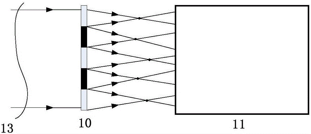
[0047] like figure 1 As shown, the laser far-field focal spot high-precision dynamic diagnosis device provided by the present invention includes a collimator mirror 2 and an iris diaphragm 3 arranged sequentially on the output laser light path of the single-mode fiber laser 1 (the diameter of the diaphragm aperture depends on the measured laser Beam aperture selection of beam 13), beam splitter 4, beam reduction / expansion system 7, reflector 8, multi-channel binary optical element 10, CCD detector 11, and reference is set on the reflection optical path of beam splitter 4 Integrating sphere power meter 5, measuring integrating sphere power meter 9 is set on the reflected optical path of reflector 8; The present invention also includes the control that links with reference integrating sphere power meter 5, measuring integrating sphere power meter 9, CCD detector 11 simultaneously computer12.

[0048] The fiber end face of the single-mode fiber laser 1 is placed at the focal poi...


PUM


Abstract

The invention provides a laser far-field focal spot high-precision dynamic diagnosis device and method, and aims to overcome the defects that the prior art is low in resolution ratio and large in error.The dynamic diagnosis device comprises a single mode fiber laser device, a collimating mirror, an iris diaphragm, a beam splitter, a sampling mirror, a beam shrinking and expanding system, a reflective mirror, a multi-channel binary optical element and a CCD detector which are sequentially arranged on the same optical path.The dynamic diagnosis device further comprises a reference integrating sphere power meter arranged on the reflecting optical path of the beam splitter, a measurement integrating sphere power meter arranged on the reflecting optical path of the reflective mirror and a control computer connected with the reference integrating sphere power meter, the measurement integrating sphere power meter and the CCD detector at the same time.Far-field focal spot diagnosis of laser beams in different calibers can be achieved; the dynamic diagnosis device has the advantages of being high in accuracy and stability, and measurement results are high in confidence coefficient.

Description

technical field [0001] The invention belongs to the field of optics, and relates to a high-precision dynamic diagnosis device and a diagnosis method for a laser far-field focal spot based on a multi-channel binary optical technology and a phase recovery method. Background technique [0002] The intensity distribution of the laser far-field focal spot is an important indicator of the quality of the laser beam, and it is also the main parameter that characterizes the ability of the laser beam to enter the hole in the high-energy laser system. The far-field distribution of the laser determines the focusability of the beam and indirectly reflects the wavefront condition. Accurate measurement of the far-field focal spot is crucial to the correct evaluation of beam quality evaluation parameters such as beam quality β factor and encircling energy ratio. There are two main difficulties in the measurement of the high-energy laser far-field focal spot: (1) the intensity distribution ...

Claims


Application Information

Patent Timeline
Patent Type & Authority Applications(China)
IPC IPC(8): G01J1/42G01J9/00
CPCG01J1/4257G01J9/00G01J2009/002
Inventor 段亚轩李晶陈永权赵建科刘尚阔田留德李坤王涛薛勋赵怀学潘亮
Owner XI'AN INST OF OPTICS & FINE MECHANICS - CHINESE ACAD OF SCI
Why Eureka
Try Eureka