Speed ​​sensor assembly of high-speed vehicle motor and manufacturing method thereof

A speed sensor, high-speed car technology, applied in the direction of linear/angular speed measurement, speed/acceleration/shock measurement, speed/acceleration/electric shock meter detailed information, etc., can solve problems such as pad damage, motor failure, loose hidden dangers, etc. Achieve the effects of improving the overall strength and watertightness, facilitating production management and improving reliability

Active Publication Date: 2019-02-26
NINGBO CRRC TIMES TRANSDUCER TECH CO LTD
View PDF7 Cites 0 Cited by
  • Summary
  • Abstract
  • Description
  • Claims
  • Application Information

AI Technical Summary

Problems solved by technology

[0004] 1. The front end of the sensor seat needs to be connected by screws. The screw connection has potential loosening hazards. After the screws are loose, the cover plate and screws will fall into the traction motor, causing motor failure
[0005] 2. The connection method between the printed board and the cable is pad soldering. Since the core wire of the cable is relatively thick, the amount of tin enamel during soldering is large, and the pad is easily damaged and peeled off when the pad is heated for a long time. After wire soldering, a large external force is applied to the pad, which is easy to cause desoldering
[0006] 3. Only rely on sealant to isolate the printed board components and the metal shell such as the seat, and the pressure resistance level is low
[0007] 4. The size of the interface between the seat and the cover plate is large, and there is no other effective sealing structure except the sealant, resulting in poor watertightness of the sensor as a whole
[0008] 5. When the waterproof pipe joint locks the cable, the printed board assembly is similar to a cantilever beam structure, which is easy to introduce deformation and internal stress, resulting in desoldering of components on the printed board

Method used


Image

  • Speed ​​sensor assembly of high-speed vehicle motor and manufacturing method thereof
  • Speed ​​sensor assembly of high-speed vehicle motor and manufacturing method thereof
  • Speed ​​sensor assembly of high-speed vehicle motor and manufacturing method thereof

Examples


Embodiment Construction

[0033] The present invention will be further described below in conjunction with the embodiments of the accompanying drawings.

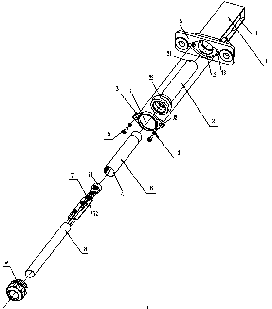
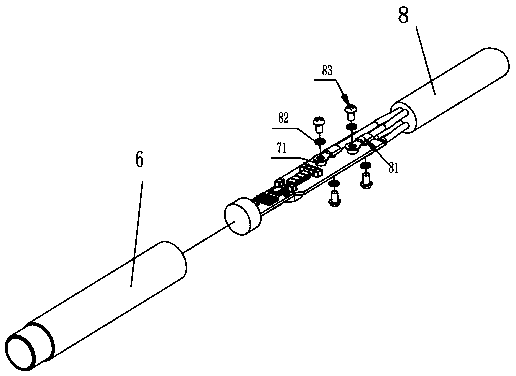
[0034] Such as Figure 1-7 As shown, the speed sensor assembly of a high-speed vehicle motor includes an outer shell 1, an inner shell 2, a gland 3, a printed board casing 6, a printed board assembly 7, a cable 8, and a waterproof pipe joint 9.

[0035] The head of the outer shell 1 is provided with the mounting hole 11 of the head 2 of the inner shell, and the tail of the outer shell 1 is a mounting part 15, and a gland hole 12 and an mounting hole 13 of the inner shell are respectively arranged on the mounting parts.

[0036] Hollows 11 are also provided on both sides of the housing 1, which can reduce the weight of the product without affecting the structural strength.

[0037] The above-mentioned inner shell 2 is an inner hollow cavity, the cavity head 21 is closed, the cavity head 21 extends out of the shell installation hole 11 and is limited ...


PUM


Abstract

A speed sensor assembly of a motor for a high-speed vehicle comprises an outer shell, an inner shell, a gland, a printed board protecting barrel, a printed board assembly, a cable and a waterproof pipe connector.The head of the outer shell is provided with an installation hole for the head of the inner shell, the tail of the outer shell serves as an installation part, and the installation part is provided with a gland hole and an inner shell installation hole.The inner shell is a cavity, the head of the cavity is closed, stretches out of the installation hole in the outer shell and is limited by the installation hole, the tail of the cavity is provided with an installation part, the installation part is embedded in the inner shell installation hole in the tail of the outer shell, and the installation part is provided with an inner thread matched with the waterproof pipe connector.The gland is through in the middle and can be buckled to the installation part of the inner shell, the two sides of the gland are provided with installation parts, and the inner shell is pressed on the gland hole in the installation part of the outer shell through the installation parts.The printed board assembly is provided with a wiring terminal, and the wiring terminal is used for being connected with an insulating tip at the end of the cable so that the printed board assembly and the cable can be connected together.The speed sensor assembly is convenient to assemble, convenient to adjust and good in performance.

Description

technical field [0001] The invention relates to a speed sensor housing part. Background technique [0002] The existing EMU traction motor matching speed sensor is mainly composed of a device seat, a cover plate, a sensor head shell, a printed board assembly, a waterproof pipe joint and a cable. The assembly steps are as follows: the cable is soldered to the printed circuit board. Then put it into the sensor head shell along the X direction, and realize the fixation between the two by pouring glue in the inner cavity of the sensor head shell, so that the cables, printed boards The component and the sensor head shell are assembled into an inner core component; the inner core component is installed into the inner cavity of the seat along the X direction until the stepped surface of the outer surface of the sensor head shell withstands the stepped surface of the inner cavity of the seat, and the X direction is Rotate the axis, rotate the inner core assembly, and adjust the pha...

Claims


Application Information

Patent Timeline
Patent Type & Authority Patents(China)
IPC IPC(8): G01P1/00G01P1/02G01P3/00
CPCG01P1/00G01P1/02G01P1/026G01P3/00
Inventor 陈增贤张燕亮周冲刘丹
Owner NINGBO CRRC TIMES TRANSDUCER TECH CO LTD
Why Eureka
Try Eureka