Small DC motor testing device

A test device and small motor technology, which can be used in motor generator testing and other directions, can solve problems such as energy loss, and achieve the effects of improving energy utilization, high static error, and wide speed regulation range.

Inactive Publication Date: 2016-07-27
CRRC LUOYANG CO LTD
View PDF0 Cites 1 Cited by
  • Summary
  • Abstract
  • Description
  • Claims
  • Application Information

AI Technical Summary

Problems solved by technology

The energy generated by the original test motor M4 is directly consumed on the resistive load, resulting in a huge energy loss

Method used


Image

  • Small DC motor testing device
  • Small DC motor testing device

Examples


Embodiment Construction

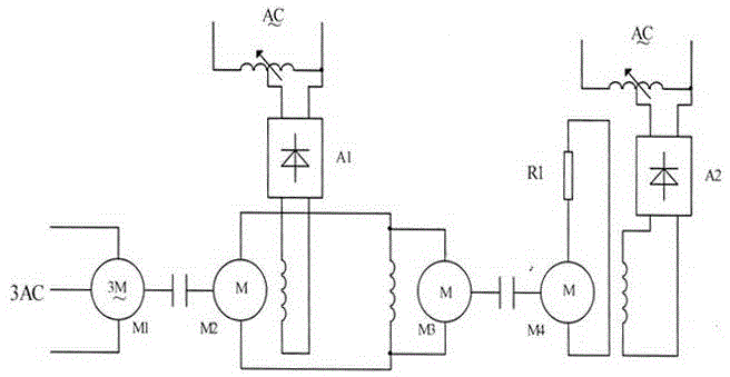
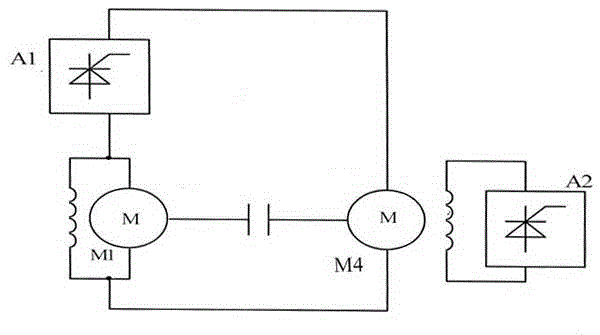
[0009] Such as figure 2 As shown, the test circuit of the present invention is that the power circuit of the tested motor M1 is connected in series with the thyristor booster power supply A1 and the accompanying test motor M4, and adjusting the thyristor booster power supply A1 can play the role of regulating the voltage of the tested motor M1, so that During the test, the rotating speed is stable; in the test circuit of the present invention, a thyristor exciter power supply A2 is provided, and the thyristor exciter power supply A2 is composed of a thyristor controller and a current and voltage feedback loop, and the current feedback of the thyristor exciter power supply A2 is connected in series to the accompanying In the excitation circuit of the test motor M4, the voltage feedback is connected in parallel to the power circuit of the accompanying test motor M4 to form a double closed-loop control system with the current closed loop as the inner loop and the voltage closed l...


PUM


Abstract

The invention discloses a small DC motor testing device, and relates to a small DC motor testing device for detecting performance parameters of a motor under various load conditions. The testing device mainly solves problems that in the prior testing devices, converter sets are high in start noise and during long-term operation, the motors have specific wear and high power consumption, and energy generated by original test accompanying motors is directly consumed on resistive loads so that energy loss is caused. The testing device comprises a tested motor M1 and a test accompanying motor M4 connected through a coupler. The testing device is characterized in that a power circuit of the tested motor M1 is serially connected with a power supply A1 of a thyristor booster, and an exciter power supply A2 which provides excitation current to the test accompanying motor M4 is arranged in a test circuit. Both of the power supply booster and the exciter adopt a thyristor controllable rectifier device and a double-closed control system in which a current closed-loop is an internal loop and a voltage closed-loop is an external loop. The testing device is noise-free, wear-free, quick in response, low in power consumption, wide in speed regulation range and stable in operation.

Description

technical field [0001] The invention belongs to the field of DC rectification and DC motor testing, in particular to a small DC motor testing device suitable for testing performance parameters of DC motors below 4.5 kilowatts under various load conditions. Background technique [0002] Known small motor test principles such as figure 1 As shown, the tested motor M1 and the accompanying test motor M4 are mechanically coupled. First start the booster A1 to output voltage Us, and the tested motor M1 acts as a shunt-excited motor to drive the accompanying test motor M4 to rotate; start the separate excitation machine A2 to output current IL, and the accompanying test motor M4 is excited to generate electricity and generate an electric potential EF. The terminal voltage of the test motor M1 becomes UD=Us+EF. As UD increases, the motor speed also increases. Adjusting the booster A1 can make the tested motor M1 run under different terminal voltages, and the speed changes according...

Claims


Application Information

Patent Timeline
Patent Type & Authority Applications(China)
IPC IPC(8): G01R31/34
Inventor 胡少军
Owner CRRC LUOYANG CO LTD
Why Eureka
Try Eureka