
Radio frequency power amplifier output match circuit structure and designing method thereof

An output matching, RF power technology, applied in power amplifiers, amplifier input/output impedance improvement, high-frequency amplifiers, etc., can solve problems such as decline, the degree of efficiency improvement is not obvious, and the third harmonic efficiency is not well utilized.

Inactive Publication Date: 2016-07-27
GUANGDONG UNIV OF TECH
View PDF4 Cites 10 Cited by
  • Summary
  • Abstract
  • Description
  • Claims
  • Application Information

AI Technical Summary

Problems solved by technology

However, this structure is not suitable for broadband applications, and the degree of efficiency improvement is not obvious
[0007] In addition, in China CN201510057384.5, a strong harmonic suppression effect is achieved by using the combination of the second harmonic network, the third harmonic network and the broadband matching network. However, this method does not make good use of the third harmonic and thus reduce the efficiency

Method used


Image

  • Radio frequency power amplifier output match circuit structure and designing method thereof
  • Radio frequency power amplifier output match circuit structure and designing method thereof
  • Radio frequency power amplifier output match circuit structure and designing method thereof

Examples


Embodiment 1

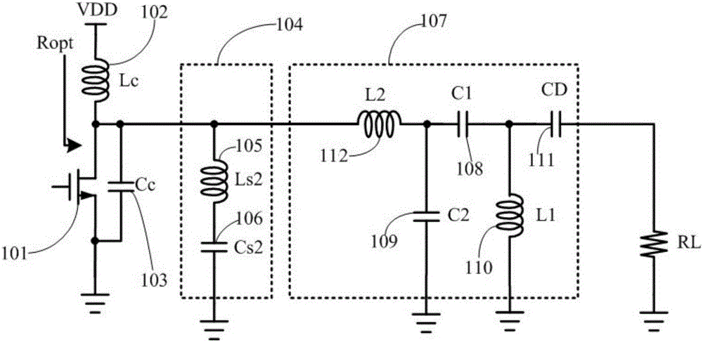
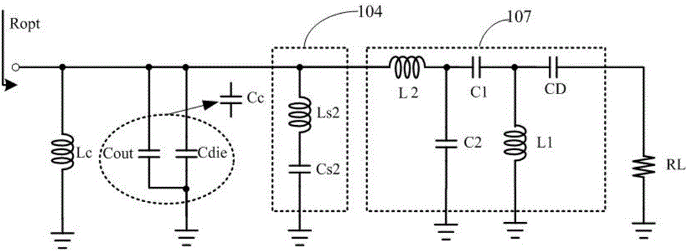
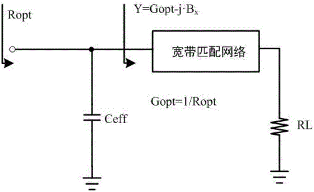
[0061] Example 1, such as Figure 1 to Figure 4 As shown, a radio frequency power amplifier output matching circuit structure, the output matching circuit includes a power amplifier tube 101, a choke inductor 102, a power amplifier tube output capacitor 103, a second harmonic network 104 and a broadband matching network 107; The harmonic network 104 is a two-terminal network composed of an inductance 105 and a capacitor 106 connected in series with one end connected to the drain (collector) of the power amplifier tube 101 and the other end is grounded; the broadband matching network 107 includes an inductance 112, an inductance 110, and a capacitor 109 A band-pass matching network composed of a capacitor 108 and a DC blocking capacitor 111; one end of the inductor 112 is connected to the drain (collector) of the power amplifier tube 101; one end of the capacitor 109 is connected to the junction of the other end of the inductor 112 and the capacitor 108 , the other end is groun...

Embodiment 2

[0062] Example 2, such as Figure 5 As shown, compared with Embodiment 1, the broadband matching network 107 adopts a two-stage low-pass LC structure, that is, the positions of the capacitor 108 and the inductor 110 in Embodiment 1 are reversed.

Embodiment 3

[0063] Example 3, such as Image 6 As shown, compared with Embodiment 1, the broadband matching network 107 adopts a two-stage high-pass LC structure, that is, the positions of the inductor 112 and the capacitor 109 in Embodiment 1 are reversed.


PUM


Abstract

The invention discloses an output matching circuit structure of a radio frequency power amplifier and a design method thereof, comprising a power amplifier tube, a choke inductor, an output end capacitance of the power amplifier tube, a second harmonic network and a broadband matching network; the second harmonic network is Two-terminal network; the broadband matching network includes a band-pass matching network composed of inductors and capacitors, and a DC blocking capacitor; the invention also provides a circuit parameter design method for an output matching circuit structure of a radio frequency power amplifier. The invention utilizes the output capacitor of the power amplifier tube, the second harmonic network and the broadband matching network to realize impedance conversion, enhances the suppression effect on the second harmonic, and makes better use of the third harmonic; thus, the output voltage of the power amplifier is improved. The waveform is closer to a square wave, and the output current is closer to a half-wave, so the overlap between the voltage waveform and the current waveform is small, which greatly improves the overall efficiency and linearity of the power amplifier, and effectively reduces the harmonic distortion of the RF power amplifier output stage.

Description

technical field [0001] The invention relates to an output matching circuit of a radio frequency power amplifier. Background technique [0002] At present, mobile networks used in portable mobile devices such as smart phones are rapidly developing and expanding around the world, and multi-function smart phones are more and more widely used. In order to provide large data transmission at high data rates, modern communication systems (3G / 4G) adopt more complex modulation methods with high spectral efficiency, such as QPSK and AQM, which combine phase shift keying and amplitude shift keying. This modulation method requires the power amplifier to have strict linearity, and the index linearity and efficiency are a pair of contradictory indicators for power amplifier design. High linearity means lower power efficiency. [0003] In order to meet the needs of different users, smart phones generally support two or more network standards, and the effective frequency bandwidth is diffe...

Claims


Application Information

Patent Timeline
Patent Type & Authority Applications(China)
IPC IPC(8): H03F1/02H03F1/56H03F3/20H03F3/189
CPCH03F1/02H03F1/56H03F3/189H03F3/20
Inventor 林俊明章国豪张志浩余凯郑耀华
Owner GUANGDONG UNIV OF TECH
Learn More