Oscillation wave power generation system

A power generation system and wave energy technology, applied in ocean energy power generation, engine components, machines/engines, etc., can solve problems such as bulky volume, low conversion efficiency, complex design, etc., and achieve a small overall space volume, simple structure, and detachable. powerful effect

Active Publication Date: 2018-11-23
WUHAN UNIV OF TECH
View PDF7 Cites 0 Cited by
  • Summary
  • Abstract
  • Description
  • Claims
  • Application Information

AI Technical Summary

Problems solved by technology

[0003] The above-mentioned oscillating water column type wave energy conversion system has the following disadvantages: bulky, complex design, and low conversion efficiency

Method used


Image

  • Oscillation wave power generation system
  • Oscillation wave power generation system
  • Oscillation wave power generation system

Examples


Embodiment Construction

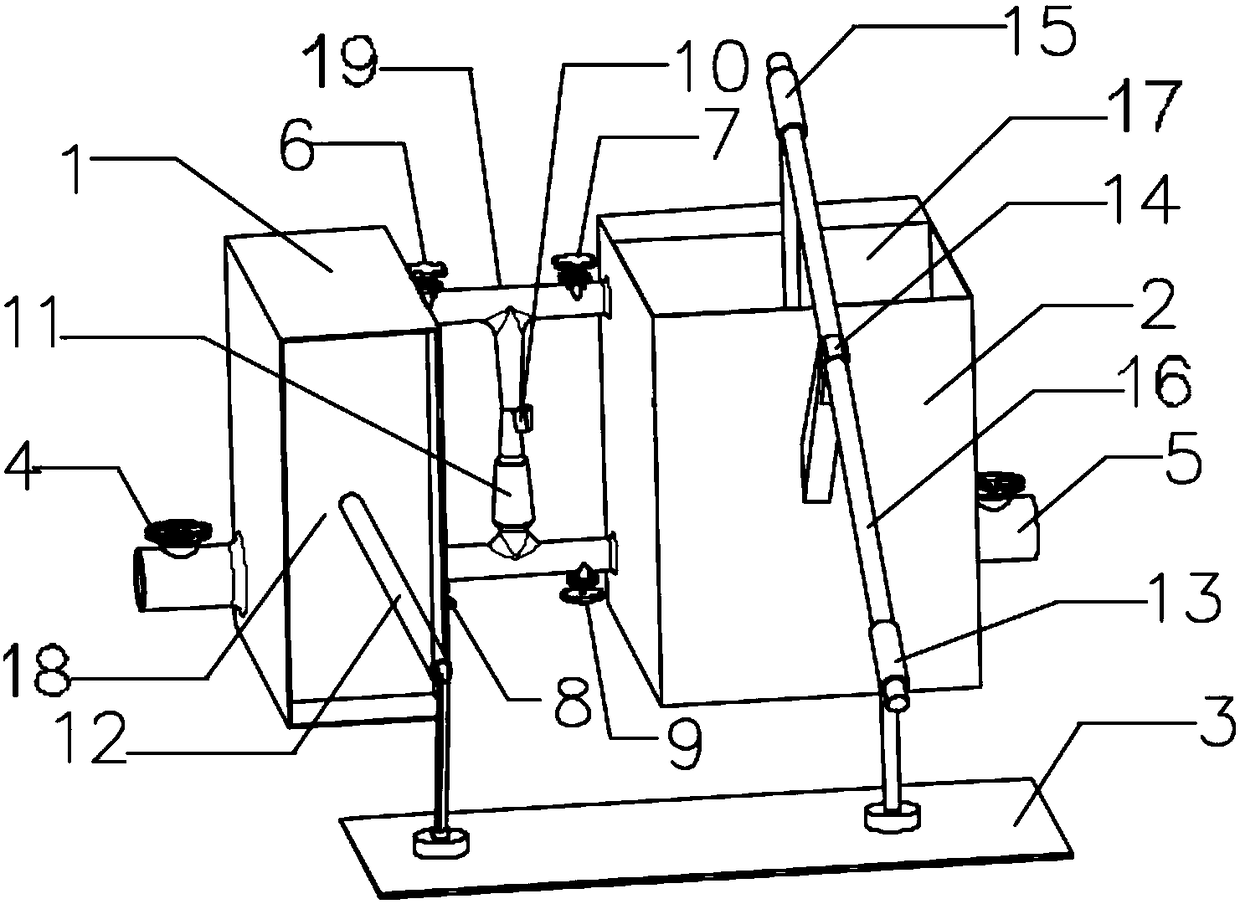
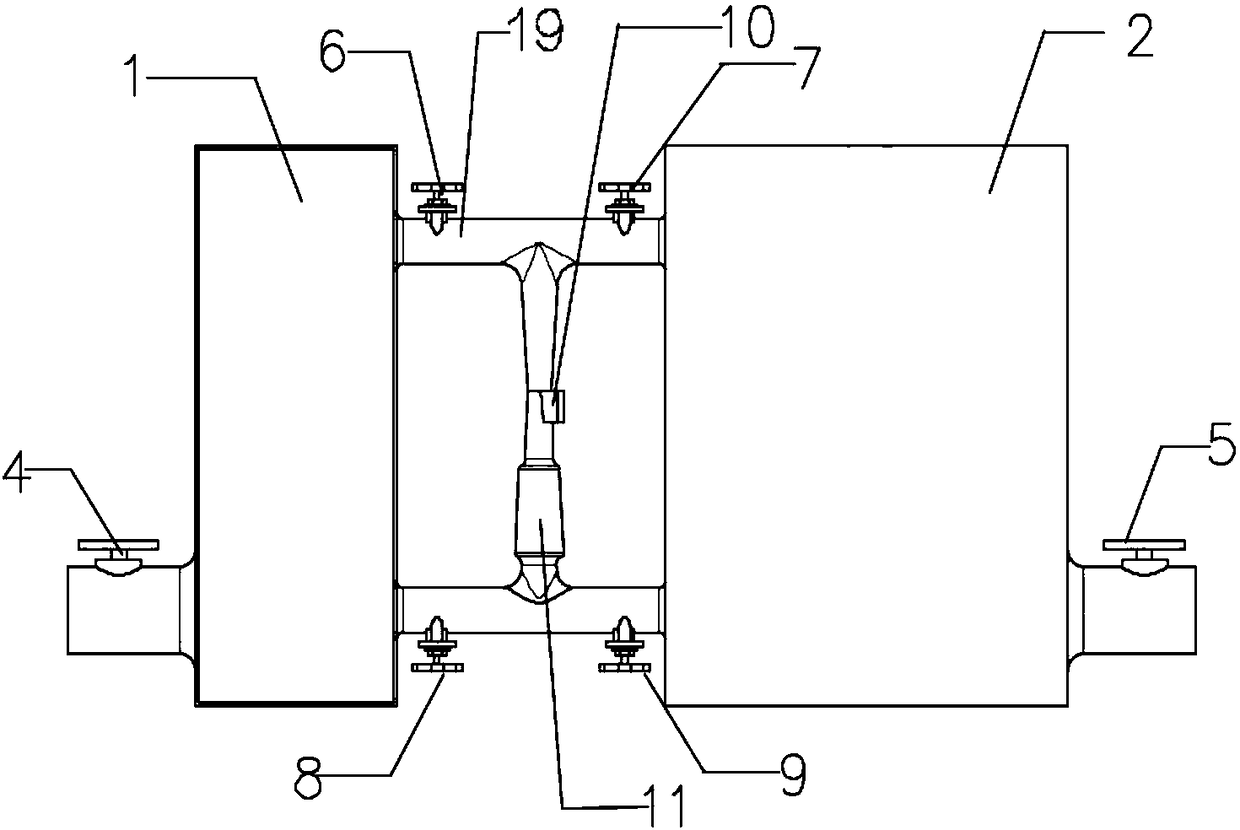
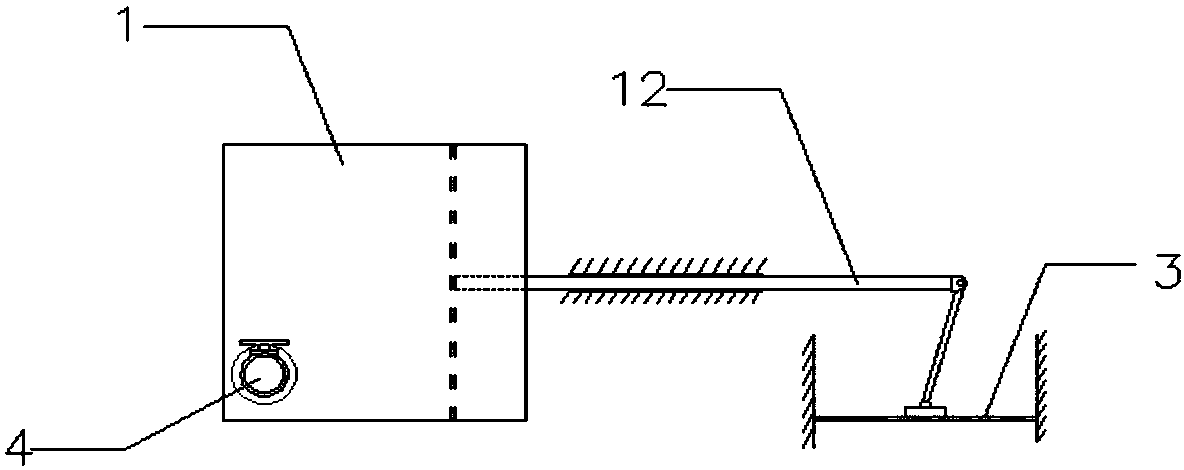
[0032] The invention provides an oscillating wave energy power generation system, comprising: a wave absorbing device, an energy conversion device and an energy output device. In the energy conversion device, when the wave crest comes, the piston on the left side moves in the horizontal direction, and the piston on the right side moves in the vertical direction, so that the two pistons respectively compress and suck the liquid in the wave-energy sealed tank to form a stronger The kinetic energy of the liquid improves the conversion efficiency of wave energy; the water delivery pipeline adopts the H-shaped pipeline design so that the reciprocating fluid in the liquid tank passes through the turbine in the energy output device from the same direction, which improves the power generation efficiency; The filter under the flat machine makes the sewage be continuously purified and discharged after a certain period. Conversely, the same is true when the trough comes.

[0033] The pr...


PUM


Abstract

The invention discloses an oscillating wave power generation system. The system is mainly composed of an energy absorption device used for absorbing wave energy, an energy conversion device used for converting the obtained wave energy into liquid flowing kinetic energy and an energy output device using the obtained liquid flowing kinetic energy to drive a generator. The oscillating wave power generation system has the advantages of being high in generation efficiency and practicality, having the sewage treatment function, and being small in overall space volume, simple in structure, low in manufacturing cost, convenient to manufacture and use, high in detachability and the like.

Description

technical field [0001] The invention relates to power generation equipment, in particular to an oscillating wave energy power generation system. Background technique [0002] The existing oscillating water column wave energy conversion system for power generation has a secondary energy conversion mechanism, wherein: the primary energy conversion mechanism is an air chamber, the seaport in its lower part is connected with seawater, and the upper part is also opened (nozzle) and connected with the atmosphere : Under the action of wave force, the water column in the lower part of the air chamber oscillates up and down in the air chamber, and the air in the compressed air chamber reciprocates through the nozzle to convert the wave energy into the pressure energy and kinetic energy of the air. The secondary energy conversion mechanism is an air turbine, which is installed on the nozzle of the air chamber. The pressure energy and kinetic energy of the air can drive the air turbine...

Claims


Application Information

Patent Timeline
Patent Type & Authority Patents(China)
IPC IPC(8): F03B13/14
CPCF03B13/14Y02E10/30
Inventor 朱凌王锐陈壮张恒戴佳莉魏思行
Owner WUHAN UNIV OF TECH
Why Eureka
Try Eureka