Decoupling film rigidity-variable semi-active suspension

A technology of semi-active suspension and decoupling membrane, which is applied in the direction of power plant, jet propulsion device, internal combustion propulsion device, etc. It can solve the problems of difficulty in mass production, high price, and small controllable range of damping, so as to solve the problems of stiffness and Damping requirements, reducing high-frequency dynamic hardening, and improving ride comfort

Active Publication Date: 2016-08-03
ASIMCO NVH TECH CO LTD ANHUI
View PDF8 Cites 4 Cited by
  • Summary
  • Abstract
  • Description
  • Claims
  • Application Information

AI Technical Summary

Problems solved by technology

Among them: the air spring type mainly forms an air cavity between the decoupling membrane and the inertial channel, and controls the connection between the air cavity and the atmosphere through the opening and closing of a small hole to adjust the stiffness. The sealing of the air cavity in this way is not easy to solve; The flow channel type is mainly to directly connect the upper and lower liquid chambers at high frequencies. This method has a complex structure, difficult sealing, and requires high control accuracy for the stepping motor; while the electrorheological and magnetorheological types are applied The electric field or magnetic field changes the viscosity of the damping fluid, thereby changing the damping, but the magnetic particles in the liquid in this way are easy to settle, and the controllable range of the damping is small
However, the structure and processing technology of the active mount are complex and expensive, and it is difficult to achieve mass production with the current technical level.

Method used


Image

  • Decoupling film rigidity-variable semi-active suspension
  • Decoupling film rigidity-variable semi-active suspension
  • Decoupling film rigidity-variable semi-active suspension

Examples


Embodiment Construction

[0025] It should be noted that, in the case of no conflict, the embodiments in the present application and the features in the embodiments can be combined with each other; the present invention will be described in detail below with reference to the accompanying drawings and in combination with the embodiments.

[0026] refer to figure 1 , 2 , 3:

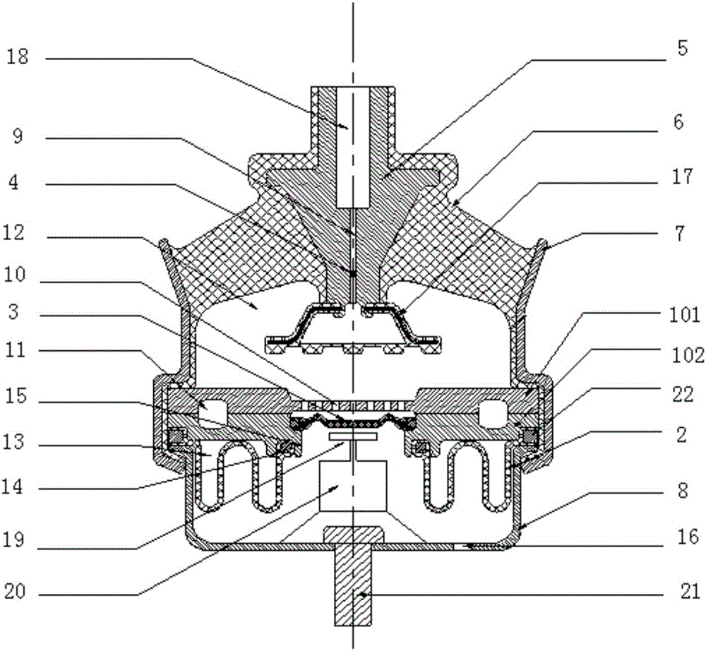
[0027] A decoupling membrane rigidity variable semi-active mount proposed by the present invention includes a housing assembly, a flow channel assembly, a leather cup 2, a decoupling membrane 3, a seal 4, a driving mechanism, and a spoiler 17;

[0028] The housing assembly includes an inner core 5, a rubber main spring 6, an outer frame 7, and a base 8. The inner core 5 is provided with a mounting hole 18 and a liquid inlet hole 9; the first end of the liquid inlet hole 9 is connected to the mounting hole 18 , the second end of the liquid inlet hole 9 is connected with the upper liquid chamber 12; the mounting hole 18 can be a thr...


PUM


Abstract

The invention discloses a decoupling film rigidity-variable semi-active suspension. The decoupling film rigidity-variable semi-active suspension comprises a shell module, a runner module, a leather bowl, a decoupling film, a sealing piece and a driving mechanism; the shell module includes an inner core, a rubber main spring, an outer skeleton and a base; a liquid inlet hole is formed in the shell module; the inner core, the rubber main spring, the outer skeleton and the base surround an accommodating space; the runner module is positioned in the accommodating space, and is provided with a liquid passing hole and an inertia channel; an upper liquid cavity is formed between one side surface of the runner module and the rubber main spring, and is communicated with the external through the liquid inlet hole; and in order to conveniently mount and machine, the runner module can be divided into two parts: an upper runner plate and a lower runner plate. The leather bowl is positioned on one side, far from the upper liquid cavity, of the runner module; a lower liquid cavity is formed between the leather bowl and the runner module, and is communicated with the upper liquid cavity through the inertia channel; the decoupling film is positioned on one side, far from the upper liquid cavity, of the runner module; and the accommodating space is formed between the decoupling film and the runner module, and is communicated with the upper liquid cavity through the liquid passing hole. The decoupling film rigidity-variable semi-active suspension is simple in structure and convenient for use.

Description

technical field [0001] The invention relates to the technical field of engine semi-active hydraulic mount systems, in particular to a semi-active mount with variable decoupling membrane stiffness. Background technique [0002] At present, people have higher and higher requirements for the ride comfort of automobiles, but the vibration isolation technology of the engine, which is the main vibration source, has always been a difficult problem for people. In this regard, people have taken many methods to isolate engine vibration and reduce noise. For example, pure rubber block suspension was used at the beginning, but its damping was low and the vibration isolation effect was not good; later, people used a hydraulic suspension structure combining rubber and hydraulic pressure to increase damping. The development of ordinary hydraulic mounts has gone through the process from the orifice type to the inertial channel type, from the inertial channel decoupling membrane type to the...

Claims


Application Information

Patent Timeline
Patent Type & Authority Applications(China)
IPC IPC(8): F16F13/10B60K5/12
CPCB60K5/12B60K5/1208F16F13/105F16F13/107
Inventor 郑帅
Owner ASIMCO NVH TECH CO LTD ANHUI
Why Eureka
Try Eureka