Eureka AIR delivers breakthrough ideas for toughest innovation challenges, trusted by R&D personnel around the world.

Pattern plating method for integrating two types of sheet resistance film circuits on same plane of dielectric substrate

A dielectric substrate and graphic electroplating technology, which is applied in the direction of circuits, electrical components, electrical solid devices, etc., can solve the problems of metal plating points on the resistance layer and low graphic accuracy, and reduce the risk of scratching conductor graphics and graphic resolution. High and improve the effect of circuit yield

Active Publication Date: 2016-08-03
THE 41ST INST OF CHINA ELECTRONICS TECH GRP
View PDF3 Cites 8 Cited by
  • Summary
  • Abstract
  • Description
  • Claims
  • Application Information

AI Technical Summary

Problems solved by technology

[0005] The purpose of the present invention is to provide a kind of graphic electroplating method integrating two kinds of square resistance film circuits on the same plane of the dielectric substrate, to solve the problem of the existing thin film circuit electroplating of two kinds of square resistance on the same plane of the dielectric substrate. It is easy to produce metal plating spots and low graphics accuracy on the resistance layer

Method used


Image

  • Pattern plating method for integrating two types of sheet resistance film circuits on same plane of dielectric substrate
  • Pattern plating method for integrating two types of sheet resistance film circuits on same plane of dielectric substrate
  • Pattern plating method for integrating two types of sheet resistance film circuits on same plane of dielectric substrate

Examples


Embodiment 1

[0036] The NiCr / TaN / TiW / Au films are sequentially deposited on the same plane of the alumina dielectric substrate, taking the electroplating of thin film circuit patterns with two different square resistances of TaN and NiCr as an example:

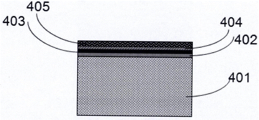
[0037] First, a dielectric substrate 401 is provided, such as Figure 3a As shown, the dielectric material is a 2in×2in square aluminum oxide substrate with a purity of 99.6%-100%, a thickness of 0.254mm, single-sided polishing, and a roughness of ≤1μin. After the dielectric substrate 401 is cleaned, NiCr / TaN / TiW / Au thin films are sequentially sputtered on the polished surface using a magnetron sputtering process. Among them, the large resistance film material 402 is a 200Ω / NiCr film, the small resistance film material 403 is a 9.5Ω / TaN film, the adhesive layer film material 404 is a TiW film, and the conductive layer film material 405 is an Au film.

[0038] Next, the electrode pattern is made into a photolithographic first mask. A laye...

Embodiment 2

[0044] NiCr / Ta / Ti / Au films are sequentially deposited on the same plane of the sapphire dielectric substrate, taking the electroplating of thin film circuit patterns with two different resistances of Ta and NiCr as an example:

[0045] First, a dielectric substrate 401 is provided, such as Figure 3a As shown, the dielectric material is a circular sapphire substrate with a diameter of 2in, a thickness of 0.254mm, double-sided polishing, and a roughness of ≤1μin. After the dielectric substrate 401 is cleaned, NiCr / Ta / Ti / Au thin films are sequentially sputtered on the polished surface using a magnetron sputtering process. Among them, the large resistance film material 402 is a 250Ω / NiCr film, the small resistance film material 403 is a 10Ω / Ta film, the adhesive layer film material 404 is a Ti film, and the conductor layer film material 405 is an Au film.

[0046] Next, the electrode pattern is made into a photolithographic first mask. Spin-coat a layer of RZJ-390PG photoresist...


PUM

PropertyMeasurementUnit
thicknessaaaaaaaaaa
thicknessaaaaaaaaaa
diameteraaaaaaaaaa

Abstract

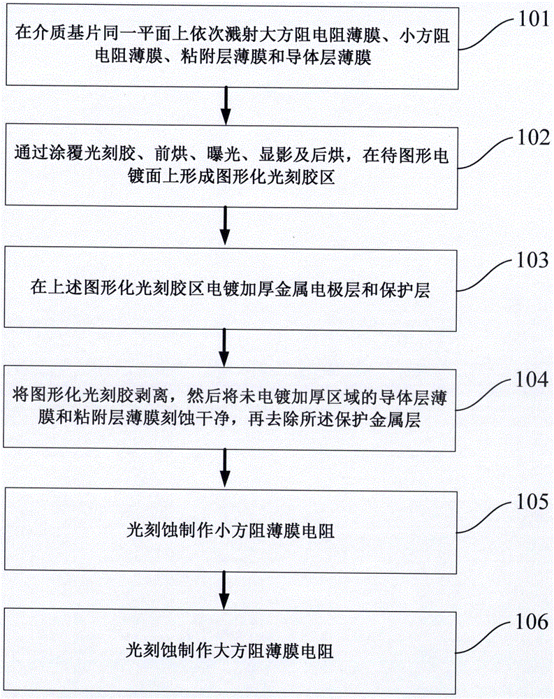
The invention provides a pattern plating method for integrating two types of sheet resistance film circuits on the same plane of a dielectric substrate, comprising the following steps: sequentially sputtering a large-sheet-resistance resistive film, a small-sheet-resistance resistive film, an adhesion layer film and a conductor layer film on the same plane of a dielectric substrate; applying photoresist and carrying out pre-baking, exposing, developing and post-baking to form a graphical photoresist area on a surface to be pattern-plated; plating a thickened metal electrode layer and a protective layer in the graphical photoresist area; stripping the graphical photoresist, fully etching the conductor layer film and the adhesion layer film in the non-plated and non-thickened area, and removing the protective metal layer; making a small-sheet-resistance film resistor through photo-etching; and making a large-sheet-resistance film resistor through photo-etching. A circuit pattern made by the method has the advantages of small lateral growth of conductor patterns, steep line edge, high pattern resolution, and the like.

Description

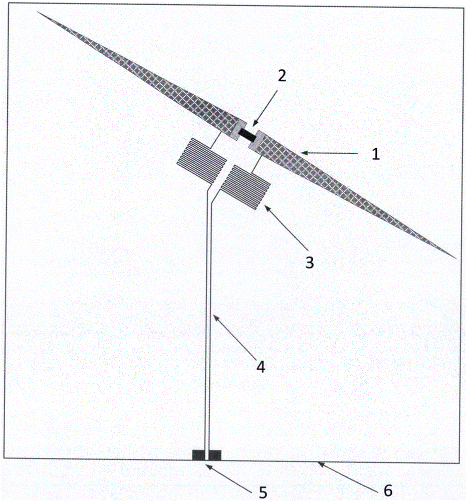
technical field [0001] The invention relates to the technical field of manufacturing microwave and millimeter wave thin film circuits, in particular to a pattern electroplating method for integrating two square resistance thin film circuits on the same plane of a dielectric substrate. Background technique [0002] An electric field radiation broadband detector based on distributed thin film resistance loading is suitable for radio frequency broadband electric field radiation detection in the near and far field full space area. The scheme adopts electric small probes loaded with distributed thin-film resistors to receive broadband electric field radiation, and then detects electric field radiation through high-sensitivity low-barrier Schottky diodes, and passes the detection signal through a low Pass filter RF signal isolation, so as to achieve the purpose of low distortion output. Electric field radiation broadband detector based on distributed thin film resistance loading,...

Claims


Application Information

Patent Timeline
Patent Type & Authority Applications(China)
IPC IPC(8): H01L21/70H01L27/01
CPCH01L21/707H01L27/016
Inventor 曹乾涛赵海轮孙佳文
Owner THE 41ST INST OF CHINA ELECTRONICS TECH GRP
Why Eureka
Eureka Blog
Learn More