Multi-magnetic circuit low voltage high current digital AC constant current source

A technology of AC constant current source and multi-magnetic circuit transformer, applied in the direction of converting AC power input to DC power output, electrical components, output power conversion devices, etc., can solve the problem of reducing system output efficiency, increasing line loss, uneven current And other problems, to achieve the effect of strong anti-interference, stable control signal, and improve work stability

Active Publication Date: 2019-05-17
WENZHOU UNIVERSITY +1
View PDF6 Cites 0 Cited by
  • Summary
  • Abstract
  • Description
  • Claims
  • Application Information

AI Technical Summary

Problems solved by technology

[0002] In the low-voltage and high-current field, a single inverter solution cannot meet the power output requirements, and it is often necessary to use multiple inverters in parallel to increase its output power
This kind of inverter parallel expansion scheme is simple to realize, and at the same time, low-power switching devices can be selected, which reduces the production cost. The output of the total current of the transformer, so the existence of circulating current increases the loss of the line and reduces the efficiency of the system output; at the same time, the circulating current will also cause the problem of uneven current, which will make the current stress borne by the power device IGBT tube unbalanced , affecting its service life and reducing the reliability of the parallel system

Method used


Image

  • Multi-magnetic circuit low voltage high current digital AC constant current source

Examples


Embodiment Construction

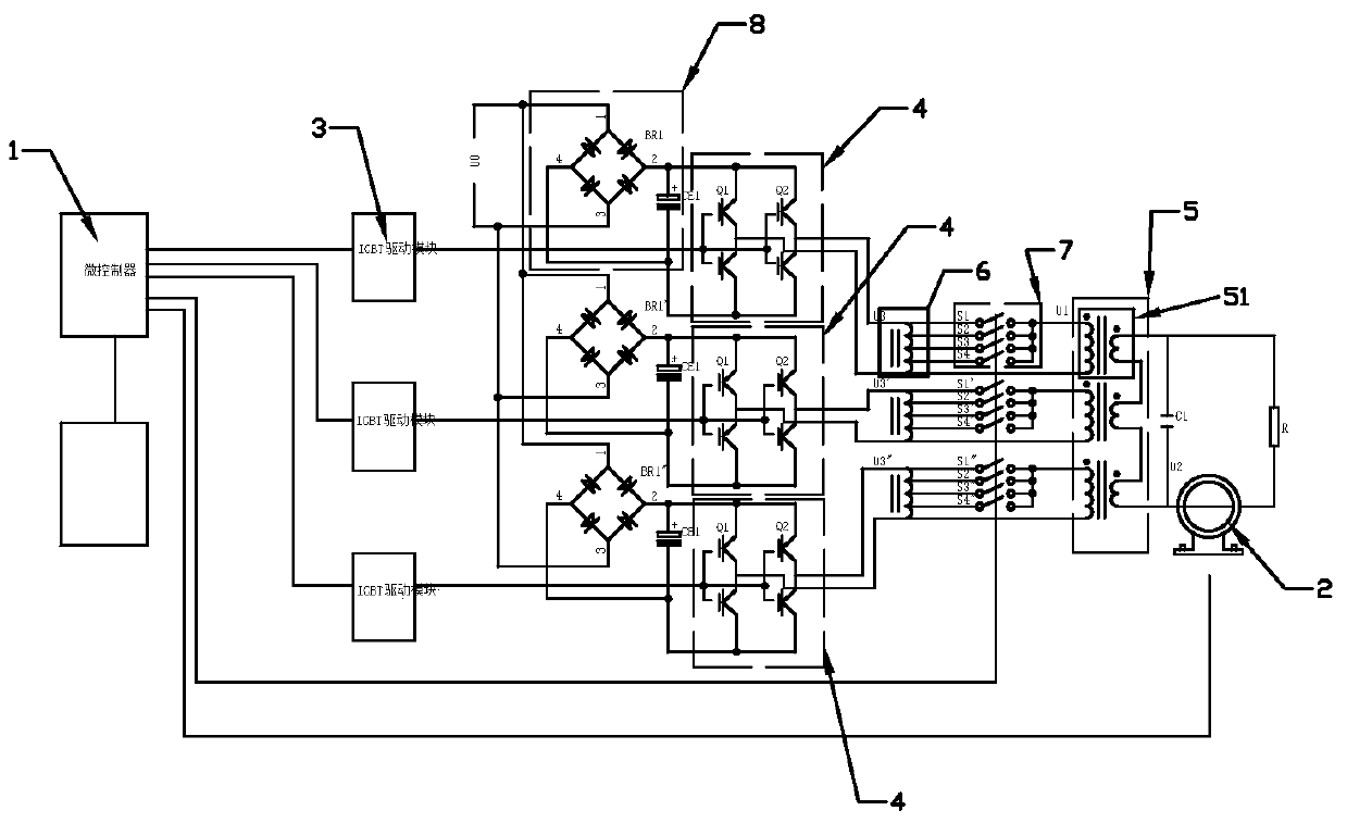
[0023] See attached figure 1 , a multi-magnetic circuit low-voltage high-current digital AC constant current source disclosed by the present invention includes a current access terminal U0 and a load terminal R, and also includes a microcontroller 1, a current transformer 2, and an H-bridge drive circuit module 3 , full-bridge circuit 4 and multi-magnetic circuit transformer 5, described multi-magnetic circuit transformer 5 includes several step-up transformers 51, and the secondary side winding of described multi-magnetic circuit transformer 5 is the secondary coil of each step-up transformer 51 Connected in series, the secondary side winding is connected to the load terminal R, the primary side winding of the multi-magnetic circuit transformer 5 is formed independently of the secondary coils of the step-up transformers 51, and each of the step-up transformers 51 is connected in one-to-one correspondence There is a full-bridge circuit 4, the output end of the full-bridge circ...


PUM


Abstract

The invention relates to a multi-magnetic-circuit, low-voltage and large-current digital AC constant current source, which comprises a current transformer, a micro-controller, H-bridge drive circuit modules, full-bridge circuits and a multi-magnetic-circuit transformer. The current transformer is used for acquiring a current signal outputted by a load side and then sending the acquired current signal to the micro-controller. The micro-controller is used for outputting control signals in one to one correspondence with the H-bridge drive circuit modules according to the control signal. The multi-magnetic-circuit transformer is formed by a plurality of current-rising transformers. The secondary winding of the multi-magnetic-circuit transformer is connected with the load side and is formed through the serial connection of the secondary coils of all the current-rising transformers. The primary winding of the multi-magnetic-circuit transformer is formed by the mutually independent secondary coils of all the current-rising transformers. The current-rising transformers, the full-bridge circuit and the H-bridge drive circuit modules are in one-to-one correspondence. The full-bridge circuits are connected with the primary coils of the current-rising transformers. The full-bridge circuits are connected with a current access end. The H-bridge drive circuit modules controls the on / off states of the full-bridge circuits according to one corresponding control signal. The multi-magnetic-circuit, low-voltage and large-current digital AC constant current source is stable in operation, strong in interference resistance, low in loss and low in cost.

Description

technical field [0001] The invention relates to a power supply device, specifically a low-voltage high-current digital AC constant current source. Background technique [0002] In the low-voltage and high-current field, a single inverter solution cannot meet the power output requirements, and it is often necessary to use multiple inverters in parallel to increase their output power. This kind of inverter parallel expansion scheme is simple to realize, and at the same time, low-power switching devices can be selected, which reduces the production cost. The output of the total current of the transformer, so the existence of circulating current increases the loss of the line and reduces the efficiency of the system output; at the same time, the circulating current will also cause the problem of uneven current, which will make the current stress borne by the power device IGBT tube unbalanced , affecting its service life and reducing the reliability of the parallel system. Con...

Claims


Application Information

Patent Timeline
Patent Type & Authority Patents(China)
IPC IPC(8): H02M7/5387
CPCH02M7/5387
Inventor 赵升陈冲许海波吴桂初许小锋吴自然
Owner WENZHOU UNIVERSITY
Why Eureka
Try Eureka