Dual-mode controller of electrical-mechanical converter

A converter and controller technology, applied in the direction of AC motor control, control system, electrical components, etc., can solve the PID controller response speed, overshoot and noise interference performance to maximize performance, poor linearity, inertia of moving parts major problems, to achieve the effect of shortening the total control time and retaining the accuracy

Inactive Publication Date: 2016-08-03
GUANGZHOU INST OF ADVANCED TECH CHINESE ACAD OF SCI +1
View PDF6 Cites 6 Cited by
  • Summary
  • Abstract
  • Description
  • Claims
  • Application Information

AI Technical Summary

Problems solved by technology

The moving coil electro-mechanical converter has attracted widespread attention for its high linearity, small hysteresis and good response characteristics. The inertia of the moving parts is large, resulting in insufficient continuous control characteristics of electrical signals, poor linearity, low precision, one-way output, slow response, and low sensitivity. It is mostly used in low-frequency and low-precision control occasions
[0003] Traditionally, PID controllers are widely used to control them. However, PID controllers are limited by contradictions such as response speed, overshoot, and noise interference, making it difficult to maximize their performance.

Method used


Image

  • Dual-mode controller of electrical-mechanical converter
  • Dual-mode controller of electrical-mechanical converter
  • Dual-mode controller of electrical-mechanical converter

Examples


Embodiment Construction

[0019] In order to make the above objects, features and advantages of the present invention more comprehensible, the technical solutions of the present invention will be described in detail below in conjunction with the accompanying drawings and specific embodiments.

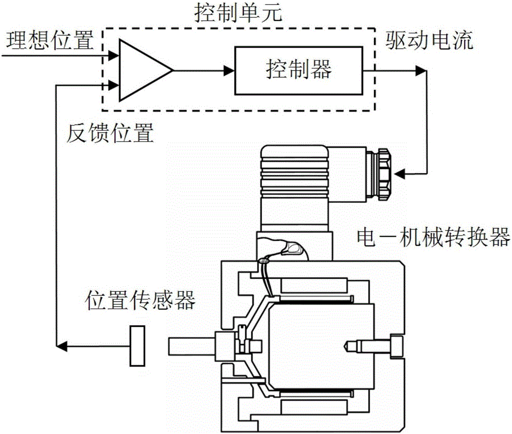
[0020] figure 1 It is the control schematic diagram of the electric-mechanical converter of the controlled object of the present invention. After the input signal is processed by the controller, it is loaded to the control coil. The current-carrying control coil and the bobbin are subjected to electromagnetic force in the constant magnetic field provided by the permanent magnet. The displacement is generated by the action, and the position error of the moving coil assembly is detected by the position sensor, which is compensated to the input signal to ensure that the moving coil assembly remains in the required correct position.

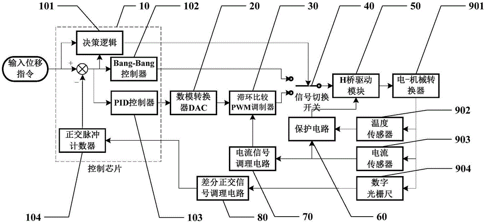
[0021] figure 2 It shows a dual-mode controller of an electro-mechanical convert...


PUM


Abstract

The present invention discloses a dual-mode controller of an electrical-mechanical converter. The dual-mode controller of the electrical-mechanical converter comprises a control chip, a digital analog converter (DAC), a hysteresis comparison PWM modulator, a current signal conditioning circuit, a difference orthogonal signal conditioning circuit, a signal switching switch, an H-bridge driving module, a protection circuit, the electrical-mechanical converter, a temperature sensor, a current sensor and a digital grating scale. An input signal and a feedback signal are processed by the signal conditioning circuits and then are sent to the control chip, the control chip determines and operates to obtain a control signal, and the control signal is sent to an H-bridge driver to drive the electrical-mechanical converter to reach an expected control objective, wherein the control chip switches between a PID closed-loop control mode and a time optimal Bang-Bang control mode according to an error signal, thereby achieving the control objective of being high in response characteristic and not losing the precision.

Description

technical field [0001] The invention relates to the technical field of motor control, in particular to a dual-mode controller satisfying the high-response control performance of a moving-coil electro-mechanical converter. Background technique [0002] The electric-mechanical converter (miniature linear motor) is the key component of the electro-hydraulic proportional control element. It can convert the electrical signal (current or voltage) input from the outside into a mechanical quantity (force or displacement) in a continuous and proportional manner. Characteristics directly affect the key characteristics of hydraulic actuators. The moving coil electro-mechanical converter has attracted widespread attention for its high linearity, small hysteresis and good response characteristics. The inertia of the moving parts is large, which leads to insufficient continuous control characteristics of electrical signals, poor linearity, low precision, one-way output, slow response, an...

Claims


Application Information

Patent Timeline
Patent Type & Authority Applications(China)
IPC IPC(8): H02P25/06
CPCH02P25/06
Inventor 张弓徐征王卫军盛亚顾星林宁梁松松
Owner GUANGZHOU INST OF ADVANCED TECH CHINESE ACAD OF SCI
Why Eureka
Try Eureka