Steam rising type radial-flow reactor

A reactor, radial flow technology, applied in chemical instruments and methods, chemical/physical processes, etc., can solve the problems of catalyst over-temperature service cycle, increase production cost, and high reactor temperature, and reduce catalyst carbon deposition or loss. Live risk, avoid local high temperature, and the effect of large circulation area

Active Publication Date: 2016-08-10
CHENGDU SEPMEM SCI & TECH
View PDF2 Cites 7 Cited by
  • Summary
  • Abstract
  • Description
  • Claims
  • Application Information

AI Technical Summary

Problems solved by technology

However, for methanol synthesis reactors, shift reactors, etc., conventional adiabatic bed radial reactors still have the problems of large heat release, high reactor temperature, difficult control, and short service life of catalysts, which increase production costs.

Method used


Image

  • Steam rising type radial-flow reactor
  • Steam rising type radial-flow reactor
  • Steam rising type radial-flow reactor

Examples


no. 1 example

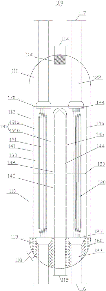
[0038] Please refer to figure 1 , the present embodiment provides a steam ascending radial flow reactor 100, which includes a reactor shell 110, a heat exchange tube bundle 120, a catalyst bed 130, a splitter tube 141, a confluence tube 142 and a confluence tube 143, and the heat exchange tube bundle 120 , the catalyst bed 130 , the splitter tube 141 , the manifold tube 142 and the manifold tube 143 are respectively arranged inside the reactor shell 110 .

[0039] In this embodiment, the reactor shell 110 includes an upper seal 111 , a middle cylinder 112 and a lower seal 113 . The upper head 111 is provided with a reaction material inlet 114 and a water vapor outlet 117 , and the lower head 113 is provided with a reaction material outlet 115 , a cooling water inlet 116 and a catalyst discharge port 118 . Wherein, the water vapor outlet 117 communicates with the top end of the heat exchange tube bank 120 , and the cooling water inlet 116 communicates with the bottom end of the ...

no. 2 example

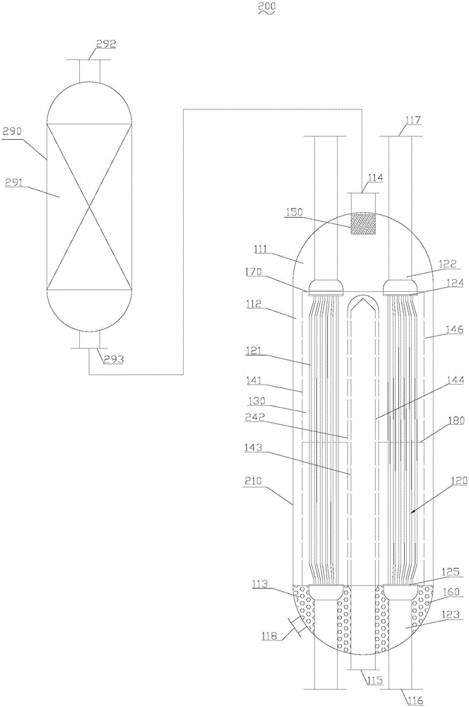
[0057] see figure 2 , this embodiment provides a steam rising radial flow reactor 200, which has roughly the same structure as the steam rising radial flow reactor 100 provided in the first embodiment, the difference between the two lies in the adiabatic The reaction section 271 is disposed outside the reactor shell 210, and the manifold 242 is made of wire mesh in this embodiment.

[0058] In this embodiment, the steam ascending radial flow reactor 200 includes a reactor shell 210 and an adiabatic reactor 290 , and the adiabatic reactor 290 communicates with the reactor shell 210 .

[0059] The adiabatic reactor 290 is provided with a pre-reaction inlet 292, an adiabatic reaction section 291 and a pre-reaction outlet 293, and the pre-reaction outlet 293 communicates with the reaction material inlet 114 of the reactor shell 210, and the adiabatic reactor 290 is located at the bottom of the reactor shell 210 The outer side, and the two are split structures, the reaction gas e...

no. 3 example

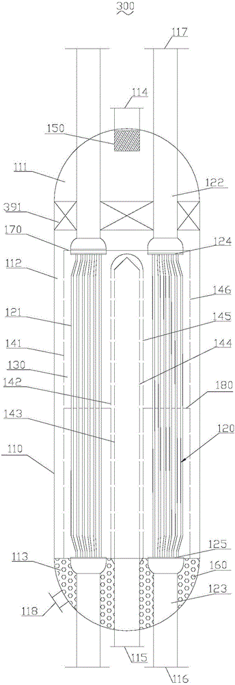
[0063] see image 3 , this embodiment provides a steam rising radial flow reactor 300, which has roughly the same structure as the steam rising radial flow reactor 100 provided in the first embodiment, the difference between the two lies in the heat insulation in this embodiment The reaction section 391 is located below the reaction material inlet 114 and above the split tube 141 .

[0064] The adiabatic reaction section 391 is located below the reaction material inlet 114 , above the distribution tube 141 , and is in contact with the water vapor collecting pipe 122 . Since the heat exchange area per unit volume of the catalyst bed in this section is small, it is regarded as an adiabatic reaction section. The reaction gas enters the reactor shell 110 from the reaction material inlet 114, and then undergoes a pre-reaction under the action of the catalyst in the adiabatic reaction section 391, and the pre-reacted reaction gas enters the split channel, and then enters the cataly...


PUM


Abstract

The invention provides a steam rising type radial-flow reactor, and relates to the field of petrochemical and coal chemical reactors. The steam rising type radial-flow reactor comprises a reactor shell, a heat exchange tube bundle, a catalyst bed, a flow diversion barrel, a flow confluence barrel, a flow confluence pipe, a reaction material inlet, a water vapor outlet, a reaction material outlet, a cooling water inlet, a catalyst discharge opening and a heat insulation reaction section; the flow diversion barrel, the flow confluence barrel and the flow confluence pipe are sequentially sleeved and communicated; the catalyst bed is arranged in a gap between the flow diversion barrel and the flow confluence barrel; the heat exchange tube bundle passes through the catalyst bed; the bottom of the flow confluence pipe is communicated with the reaction material outlet; the heat insulation reaction section is communicated with the reaction material inlet; a catalyst is arranged in the heat insulation reaction section. According to the steam rising type radial-flow reactor provided by the invention, an effect that reaction gas radially passes through the catalyst bed is achieved; a flow area is large; a pressure drop is low, and temperature distribution is uniform; the local high temperature is avoided; the carbon deposit or inactivation risk of the catalyst is effectively reduced; steam is formed as a byproduct; economic benefits are good.

Description

technical field [0001] The invention relates to the field of petrochemical and coal chemical reactors, in particular to a steam ascending radial flow reactor. Background technique [0002] In recent years, the fields of methanol synthesis, carbon monoxide shift, synthesis gas to methane, ammonia synthesis, methanol to olefins, methanol to aromatics, methanol to gasoline and other fields have gradually attracted attention, among which the research and improvement of catalytic bed reactors have always been the focus of this field. hotspot. For strong exothermic reactions in fixed beds, it is very important to effectively remove excess heat during the reaction process, maintain a stable reaction temperature, avoid carbon deposition or deactivation of the catalyst, and ensure the selectivity and yield of the reaction. [0003] According to the flow direction of the reaction materials in the reactor, the fixed bed catalytic reactor can be divided into axial flow reactor and radi...

Claims


Application Information

Patent Timeline
Patent Type & Authority Applications(China)
IPC IPC(8): B01J8/02
CPCB01J8/0221B01J8/0285B01J8/0292B01J2208/00132B01J2208/00761
Inventor 张惊涛陈小林
Owner CHENGDU SEPMEM SCI & TECH
Why Eureka
Try Eureka