Tube breaking mechanism, sealed test tube assembly comprising tube breaking mechanism and application thereof

A sealing and tube breaking technology, which is applied in the field of chromatography test paper detection devices, can solve the problems of cumbersome operation, large device volume, limitations, etc., and achieve the effect of wide application, good effect and sensitive response

Active Publication Date: 2016-08-10
QUICKING BIOTECH
View PDF11 Cites 9 Cited by
  • Summary
  • Abstract
  • Description
  • Claims
  • Application Information

AI Technical Summary

Problems solved by technology

The first is to create a closed environment in the process of detecting nucleic acid amplification products, such as: electrophoresis is carried out in a closed negative pressure room, and the reaction tube is not opened during the whole process of real-time fluorescent PCR, but these methods require strict experimental conditions And expensive experimental equipment, not suitable for popularization to grassroots users
The second is to incorporate dUTP in the nucleic acid amplification reaction, and to treat the test equipment and environment with UNG enzyme after the reaction is completed and before the next nucleic acid amplification, but this method is cumbersome to operate and has a certain probability of contamination, which limits this method. application of strategies
However, the disadvantages of this device are: 1. The device is large in size and is not suitable for large-scale production and transportation of finished products; 2. The test strips in the device are complicated to install and are not suitable for large-scale

Method used


Image

  • Tube breaking mechanism, sealed test tube assembly comprising tube breaking mechanism and application thereof
  • Tube breaking mechanism, sealed test tube assembly comprising tube breaking mechanism and application thereof
  • Tube breaking mechanism, sealed test tube assembly comprising tube breaking mechanism and application thereof

Examples


Example Embodiment

[0058] In order to make the above-mentioned objects, features and advantages of the present invention more obvious and understandable, the specific embodiments of the present invention will be described in detail below in conjunction with the accompanying drawings of the specification.

[0059] In the following description, many specific details are explained in order to fully understand the present invention, but the present invention can also be implemented in other ways different from those described here, and those skilled in the art can do it without departing from the connotation of the present invention. Similar promotion, therefore, the present invention is not limited by the specific embodiments disclosed below.

[0060] Secondly, the “one embodiment” or “embodiment” referred to herein refers to a specific feature, structure, or characteristic that can be included in at least one implementation of the present invention. The appearances of "in one embodiment" in different p...


PUM


Abstract

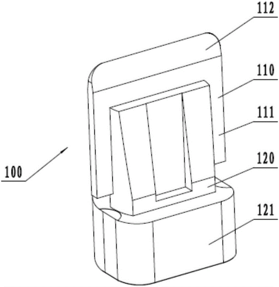
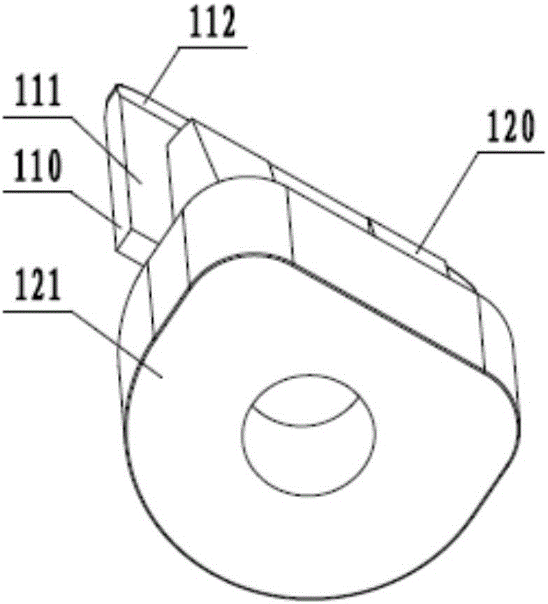
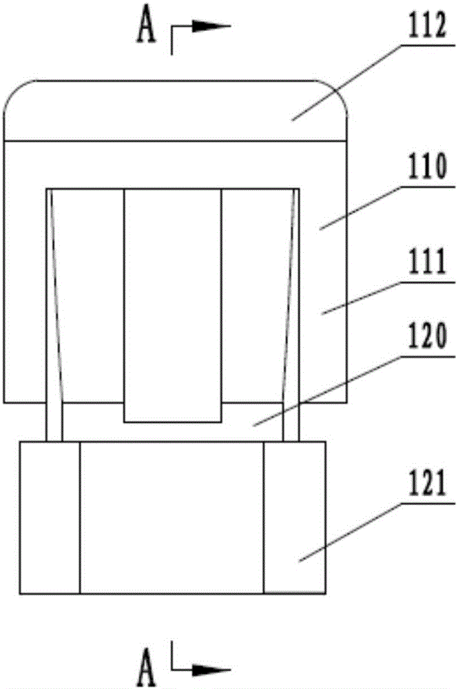
The invention discloses a tube breaking mechanism, a sealed test tube assembly comprising the tube breaking mechanism and application of the sealed test tube assembly. The tube breaking mechanism comprises a piercing component and a supporting component. The piercing component comprises a body and a shrinking part. The outer side face of the piercing component or the outer side face of the supporting component is asymmetrically distributed relative to the center of the supporting component. The sealed test tube assembly comprises the tube breaking mechanism, a solution tube and a sleeve tube. The solution tube is embedded and inserted into the sleeve tube to form a sealed and embedded bottom space. The tube breaking mechanism is located below the bottom of the solution tube embedded in the sleeve tube and used for piercing the bottom of the solution tube. After the bottom of the solution tube is pierced, at least two gap channels are formed by the outer side face of the tube breaking mechanism and a fractured hole in the bottom of the solution tube, a solution in the solution tube can flow out of the solution tube, and air in the sleeve tube can enter the solution tube. The solution tube can be pierced quite conveniently through the tube breaking mechanism. The sealed test tube assembly does not leak, is widely applied and is good in effect.

Description

technical field [0001] The invention relates to a chromatography test paper detection device, in particular to a tube breaking mechanism, a sealed test tube assembly including the tube breaking mechanism and its application. Background technique [0002] The lateral flow chromatography test paper technology (Lateral Flow, US6485982) invented by Charlton in 1988 triggered a revolution in immunological diagnosis. Solid-phase immunoreaction has achieved unprecedented simplicity, speed, precision and cheapness. Subsequently, colloidal gold immunochromatographic test paper was promoted to widely used rapid medical in vitro diagnostic reagents, and then also to the field of rapid detection of food safety and biosafety. At the same time, other dry biochemical test papers also began to use chromatography test paper. Among the detection items of these chromatography test papers, some detection substances have harmful effects on operators and the environment, such as anthrax pathoge...

Claims


Application Information

Patent Timeline
IPC IPC(8): B65B69/00G01N33/50B01L3/14
CPCB01L3/502B65B69/0041G01N33/50
Inventor 周中人姜杰沈小波张玲会
Owner QUICKING BIOTECH
Why Eureka
Try Eureka