Scanning target

A technology of scanning magnets and moving targets, applied in the field of scanning targets, can solve the problems of increasing ion beam current, reducing instantaneous and average temperature rise, transient temperature rise, etc., so as to increase ion beam current intensity and increase neutron production. Forehead, the effect of transient temperature rise reduction

Inactive Publication Date: 2016-08-10
INST OF NUCLEAR PHYSICS & CHEM CHINA ACADEMY OF
View PDF7 Cites 9 Cited by
  • Summary
  • Abstract
  • Description
  • Claims
  • Application Information

AI Technical Summary

Problems solved by technology

[0005] There are currently three ways to improve the ability of the target to withstand the deposition power: one is to use a swinging target to make the target surface mechanically swing. The advantage of this method is that the ion beam no longer just bombards the target surface without increasing the beam spot size. A point, but a surface, the average power is greatly reduced, the ion beam current can be increased, and the characteristics of the point source remain unchanged; the disadvantage is that the speed of the mechanical swing is not fast enough, the length of the expansion is limited, the volume is large, and at the same time it is rotating There is a pause at the edge of the target, and the transient temperature rise is relatively high. The deposition power density of a purely swinging target can be increased several times, and the increase is limited.
The second is "Rotating Target Intensive Neutron Source and Its Application" (Journal "Modern Physics Knowledge", No. 05, 1996) discloses a method of increasing the target area by rotating the target. The advantage of this method is that it can be used without Under the condition of increasing the beam spot size, through the high-speed rotation of the target surface, the instantaneous temperature rise and the average temperature rise are greatly reduced, thereby greatly improving the ability of the target to withstand the deposition power, thereby increasing the neutron yield and flux. The disadvantage is that the structure is complex, the volume is huge, and the rotation speed is extremely fast (1000-5000 rpm), it is very difficult to further increase the rotation speed, the reliability is poor, and the cost is high; the third is CN201010238639. A small neutron source with a window gas target. This method has the advantages of no fixed target, high output, and long target life. The disadvantage of this method is that it is extremely technically difficult, the volume of the vacuum system is large, the energy consumption is high, the cost is high, and the beam The spot scatters in the target and the point source characteristics deteriorate
[0006] At present, there is no neutron target that is economical, simple in structure, directional and point source

Method used


Image

  • Scanning target

Examples


Embodiment 1

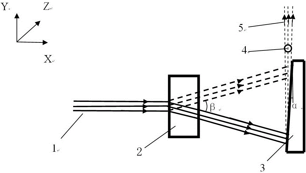
[0028] The ion beam energy of the original neutron generator system is 300keV, the current intensity is 12.5mA, the diameter of the beam spot is 15mm, the diameter of the rotating target is 200mm, the rotation speed is 1100 rpm, and the linear velocity of the bombardment area is 11.5m / s. The beam bombardment time is 0.87ms. Adopt the technology of the present invention to transform the neutron target of this system: scan the incident ion beam 1 evenly with the scanning magnet 2, expand it into a fan-shaped ion beam with a bottom length of 200mm, scan the expansion angle β to be -10°~10°, and fix the inclined plane of the target The inclination angle α ranges from 3° to 15°. In order to keep the moving speed of the beam spot on the target surface not lower than 11.5m / s, only the scanning frequency needs to be greater than 28.75Hz. Considering that the output of the 90-degree emission direction is slightly lower, and the neutron flux in the exit direction is reduced by about 10...

Embodiment 2

[0030] On the basis of Example 1, the scanning frequency is increased by about 15 times to reach 0.5kHz, the ion beam current intensity is increased by about 5 times to reach 70mA, the beam spot diameter remains unchanged, and the scanning width is expanded into a fan-shaped ion beam with a length of 400mm. The scanning expansion angle β is -20°~20°. Change the fixed target to a moving target 3, the inclination angle α of the moving target 3 ranges from 3° to 15°, and the moving target 3 translates back and forth within the range of ±50mm, and the transient temperature rise on the target surface is about lower than that of the original rotating target 6 times, and the average temperature rise is reduced by about 4 times. While effectively extending the target life, the neutron output is increased by 5 times.

Embodiment 3

[0032] The ion beam energy of the original neutron generator system is 380keV, the current intensity is 150mA, the beam spot diameter is 10mm, the rotating target diameter is 460mm, the rotation speed is 5000 rpm, the linear velocity of the bombardment area is 120m / s, and the beam current at each point The bombardment time was 0.083ms. Adopt the technology of the present invention to transform the neutron target of this system: use the scanning magnet 2 to uniformly scan and expand the incident ion beam 1 into a fan-shaped ion beam with a length of 200mm, the scanning expansion angle β is -30°~30°, and the inclined plane of the moving target 3 is inclined Angle α ranges from 3° to 15°. The moving speed of the beam spot on the target surface is not lower than 120m / s, and the scanning frequency is only required to be greater than 130Hz. Considering the slightly lower output in the 90-degree emission direction, the neutron flux in the emission direction is reduced by about 10%. ...


PUM


Abstract

The invention provides a scanning target. The scanning target is a scanning target for an accelerator neutron source. After an accelerator finishes acceleration of deuterium or deuterium-tritium mixed ion beams, ion beams are rapidly and uniformly spread into linear strip-shaped beam spots through a scanning magnetic field; spreading lengths surpass dozens of times the diameters of the beam spots; and then, the linear strip-shaped beam spots are bombarded onto a movable target in order to generate equivalent emission neutron beams having point source features in a direction parallel to a neutron target. The beam spots have high displacement speeds after scanning, and dwell time on each point is short, thereby causing low transient temperature rise. Meanwhile, a bombardment area on a target surface is uniformly widened by dozens of times; the average beam density is lowered by dozens of times; the average temperature rise is lowered greatly; and the target service life is prolonged. The scanning target is suitable for being applied to the neutron source needing directivity and a point source feature.

Description

technical field [0001] The invention belongs to the field of nuclear technology and application, and in particular relates to a scanning target. Background technique [0002] The neutron source of the accelerator uses the deuterium ions or deuterium-tritium mixed ions generated by the ion source. After being accelerated by the accelerating electric field, a certain amount of energy is obtained, and a D / D or D / T fusion reaction occurs on the target, and the neutron is released in the 4π direction. son. The neutron source of the accelerator has a high yield, no neutrons are generated after the power is turned off, it is easy to use, good in controllability and high in safety. [0003] When the high-energy ion beam of the accelerator neutron source bombards the target, high energy deposition is produced. Even under the condition of water cooling, the power density that the target can withstand must be controlled within a reasonable range to ensure the normal use of the target....

Claims


Application Information

Patent Timeline
Patent Type & Authority Applications(China)
IPC IPC(8): H05H6/00
CPCH05H6/00
Inventor 李彦何小海唐君娄本超薛小明牟云峰李小飞胡永宏
Owner INST OF NUCLEAR PHYSICS & CHEM CHINA ACADEMY OF
Why Eureka
Try Eureka