
A low-loss high-flexibility fpc board for high-frequency transmission

A high-frequency transmission and high flexibility technology, applied in the direction of flexible printed circuit boards, printed circuits, printed circuit components, etc., can solve the inconvenience of multi-antenna module integrated transmission, reduced coaxial cable diameter, increased transmission loss, etc. problem, to achieve the effect of improving integration, reducing loss and electromagnetic radiation, and low loss

Active Publication Date: 2019-03-19
KUNSHAN LONGPENG PRECISION ELECTRONICS
View PDF3 Cites 0 Cited by
  • Summary
  • Abstract
  • Description
  • Claims
  • Application Information

AI Technical Summary

Problems solved by technology

Coaxial cables have low loss during high-frequency transmission, but with the continuous pursuit of "light" and "thin" appearance design requirements of terminal equipment, the available space is continuously reduced, which leads to the constant increase in the diameter of coaxial cables. Reduced, and at the same time, it will increase the loss, which will run counter to the high capacity required by the system
On the other hand, the space requirements of coaxial cables are not convenient for the integrated transmission requirements of multi-antenna modules
Ordinary FPC can meet light and thin space requirements, but at present, traditional FPC cannot meet low-loss transmission requirements. With the continuous increase of frequency, transmission loss is also increasing. Difficult process to properly reduce the loss, which in turn will increase the cost

Method used


Image

  • A low-loss high-flexibility fpc board for high-frequency transmission

Examples


Embodiment 1

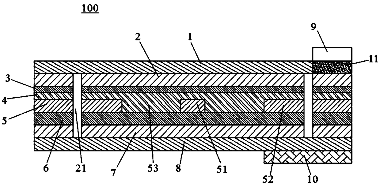
[0030] Please refer to figure 1 In this embodiment, a low-loss, high-flexibility, and high-frequency transmission FPC board 100 has a cross-sectional structure sequentially including a first solder resist layer 1, a first shielding layer 2, a first dielectric layer 3, and an adhesive layer from top to bottom. 4. Transmission line layer 5 , second dielectric layer 6 , second shielding layer 7 , and second solder resist layer 8 .

[0031] The transmission line layer 5 includes a signal line 51 formed on a central axis, and transmission areas 52 symmetrically distributed along the signal line 51 . A distance 53 is provided between the signal line 51 and the transmission area 52 .

[0032] The first solder resist layer 1 and the second solder resist layer 8 are flexible bending-resistant inks with a thickness of 12um, which are mainly used to prevent the surface of the first shield layer 2 and the second shield layer 7 made of metal from being oxidized. The surface of the first ...

Embodiment 2

[0070] The content of the second embodiment is basically the same as that of the first embodiment, the difference is that: the thickness of the first solder resist layer 1 and the second solder resist layer 8 is 18um; the thickness of the first shielding layer 2 and the second shielding layer 7 The thickness of the first dielectric layer 3 is 30um; the thickness of the bonding layer 4 is 18um; the thickness of the transmission line layer 5 is 20um; the thickness of the second dielectric layer 6 is 48um; the thickness of the reinforcing layer 10 is 1300um; The hole 21 is directly 0.15mm.

Embodiment 3

[0072] The content of the third embodiment is basically the same as that of the first embodiment, the difference is that: the thickness of the first solder resist layer 1 and the second solder resist layer 8 is 25um; the thickness of the first shielding layer 2 and the second shielding layer 7 The thickness of the first dielectric layer 3 is 50um; the thickness of the bonding layer 4 is 25um; the thickness of the transmission line layer 5 is 28um; the thickness of the second dielectric layer 6 is 75um; the thickness of the reinforcing layer 10 is 2500um; The hole 21 is directly 0.2mm.


PUM

PropertyMeasurementUnit
diameteraaaaaaaaaa
thermal resistanceaaaaaaaaaa
dielectric strengthaaaaaaaaaa

Abstract

The invention discloses an FPC with low-loss high-flexibility high-frequency transmission. The FPC comprises a first solder mask and a second solder mask, a first shielding layer and a second shielding layer which are disposed between the first solder mask and the second solder mask, a first dielectric layer and a second dielectric layer which are disposed between the first shielding layer and the second shielding layer, an adhesive layer disposed between the first dielectric layer and the second dielectric layer, and a transmission line layer disposed between the first dielectric layer and the adhesive layer, wherein the first dielectric layer and the second dielectric layer are each made of a polyimide material with a low dielectric constant. According to the invention, the low-loss requirement of high-frequency transmission can be satisfied, and at the same time, the requirement for high space integration can also be satisfied.

Description

【Technical field】 [0001] The invention belongs to the technical field of flexible circuit board manufacturing, in particular to an FPC board with low loss, high flexibility and high frequency transmission. 【Background technique】 [0002] While 4G network deployment is in full swing, research on 5G has also kicked off. In 2012, the 5G research project METIS[1] supported by the European Union's 270 billion euros was officially launched. The project is divided into eight groups for scenario requirements, air interface technology, multi-antenna technology, network architecture, spectrum analysis, simulation and test platforms, etc. In-depth research; the British government has joined forces with a number of companies to create a 5G innovation center dedicated to future user needs, 5G network key performance indicators, and core technology research, evaluation and verification; South Korea is jointly promoted by the Korean Ministry of Science and Technology, ICT and the Ministry ...

Claims


Application Information

Patent Timeline
Patent Type & Authority Patents(China)
IPC IPC(8): H05K1/02
CPCH05K1/02H05K2201/0154H05K2201/05
Inventor 曹明峰傅彬许春雷吴芳曾敏毓高德宝贾金果
Owner KUNSHAN LONGPENG PRECISION ELECTRONICS
Learn More