Ceramic shell manufacturing method and method for manufacturing ceramic shell of turbine blade

A technology of turbine blades and manufacturing methods, which are applied in the directions of manufacturing tools, casting molding equipment, casting molds, etc.

Inactive Publication Date: 2016-08-17
DONGFANG TURBINE CO LTD
View PDF6 Cites 13 Cited by
  • Summary
  • Abstract
  • Description
  • Claims
  • Application Information

AI Technical Summary

Problems solved by technology

[0004] On the one hand, the technical problem to be solved by the present invention is to provide a method for preparing a ceramic mold shell. During construction, the ceramic mold shell prep

Method used


Image

  • Ceramic shell manufacturing method and method for manufacturing ceramic shell of turbine blade
  • Ceramic shell manufacturing method and method for manufacturing ceramic shell of turbine blade
  • Ceramic shell manufacturing method and method for manufacturing ceramic shell of turbine blade

Examples


Embodiment Construction

[0037] In order to describe the technical features and functions of the present invention in detail and realize them according to the content of this specification, the implementation of the present invention will be further described below in conjunction with the accompanying drawings.

[0038] To illustrate the present invention more clearly, Figure 1 to Figure 5 A typical exemplary embodiment of a turbine blade is shown schematically.

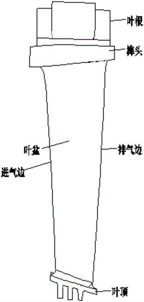
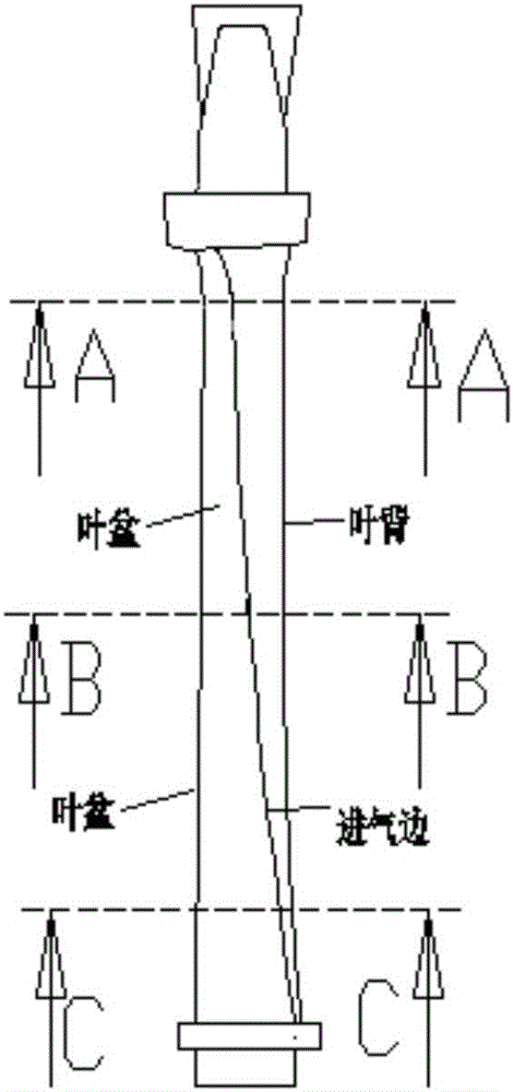
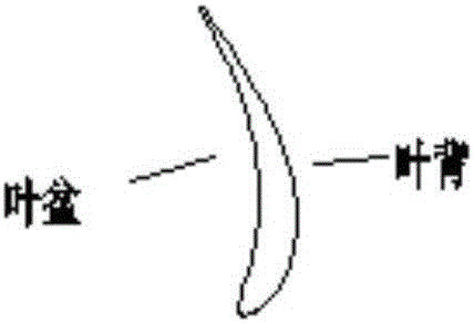
[0039] see figure 1 , 2 , the common turbine blades include gas turbine stage moving blades and stationary blades. Turbine blades generally include blade roots, tenons, blade bodies, and blade tops (stationary blades also include inner and outer edge plates). The concave surface of the blade body is the blade pot, the convex surface of the blade body is the blade back, the part receiving the impact of the airflow is the intake side, and the part where the gas flows through the turbine blades finally is the exhaust side.

[0040] Figur...


PUM

PropertyMeasurementUnit
Thicknessaaaaaaaaaa

Abstract

The invention discloses a ceramic shell manufacturing method. The ceramic shell manufacturing method comprises the following steps: step one, fixing reinforcing ribs on a part which easily deforms due to bulging at least during casting of the outside of the ceramic shell; and step two, after the ceramic shell obtained from the step one is fully dried, removing a wax mould in the ceramic shell, then removing residual wax, and roasting to obtain the required ceramic shell finally. During construction of the ceramic shell manufactured by the method, problems of heat crack of castings due to over high strength of the ceramic shell and bulging deformation of the castings due to over-low strength of the ceramic shell can be relieved at least. The invention discloses a method for manufacturing a ceramic shell of a turbine blade, and the ceramic shell manufacturing method is used.

Description

technical field [0001] The invention relates to the preparation technology of ceramic molded shells, in particular to a method for preparing ceramic molded shells and a method for preparing ceramic molded shells for turbine blades. Background technique [0002] The turbine blades of heavy-duty gas turbines are all made of lost-wax precision casting. The process of lost wax precision casting is as follows. Firstly, the wax mold of the turbine blade is pressed, the wax mold of the pouring system is pressed, and then the wax mold of the blade and the wax mold of the pouring system are assembled into a wax tree. Slurry, after the surface of the module is evenly covered with a layer of ceramic slurry, put the wax tree into the sand shower, and wait until the surface of the ceramic slurry is evenly covered with a layer of refractory sand. The high-quality refractory sand constitutes a layer of the shell, and after the layer is fully dried, the slurry and sand shower operations ar...

Claims


Application Information

Patent Timeline
IPC IPC(8): B22C9/04B22C9/22
CPCB22C9/04B22C9/22
Inventor 赵代银杨功显杨照宏张松泉曾洪何建伍林
Owner DONGFANG TURBINE CO LTD
Why Eureka
Try Eureka