Synchronous drilling device special for mine

A technology for drilling equipment and mines, applied in drilling equipment and methods, drilling equipment, drilling pipes, etc., can solve problems affecting the drilling efficiency and progress of drilling equipment, affecting the drilling speed of drilling equipment, and drilling stuck Accidents and other problems to achieve the effect of smooth protection, reduced vibration, and improved speed and quality

Active Publication Date: 2016-08-17
神木市三江能源有限公司
View PDF4 Cites 3 Cited by
  • Summary
  • Abstract
  • Description
  • Claims
  • Application Information

AI Technical Summary

Problems solved by technology

At present, the rock powder in the borehole is flushed out by pressure injection of clear water during drilling, which is beneficial to drilling; but the drilling equipment for coal mines in the prior art still needs to be improved technically, and in the actual construction process Due to strong resistance, the drilling equipment will generate strong vibrations, which will affect the drilling efficiency and process of the drilling equipment, and the strong vibrations will easily cause the drill bit to break; in addition, the actual drilling process often encounters broken rock formations, and the drilling The rock powder inside cannot be flushed out smoothly, which seriously affects the drilling speed of the drilling equipment, and sometimes even causes drilling stuck accidents, etc.

Method used


Image

  • Synchronous drilling device special for mine
  • Synchronous drilling device special for mine

Examples


Embodiment Construction

[0018] The content of the present invention will be described below in conjunction with specific embodiments.

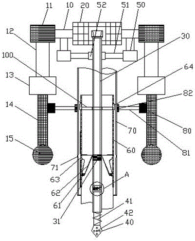
[0019] Such as Figure 1 to Figure 2 As shown, it is a structural schematic diagram of a mine-specific synchronous drilling equipment according to the present invention.

[0020] The mine-specific synchronous drilling equipment according to the present invention includes a top plate 10, a drive mechanism 20 is arranged in the middle of the top plate 10, a drill rod 30 is arranged on the drive mechanism 20, a drill bit 40 is arranged at the front end of the drill rod 30, and a drill bit 40 is located at the drive mechanism 20. The top boards 10 on both sides are provided with a first synchronous auxiliary mechanism 50, the first synchronous auxiliary mechanism 50 is provided with a first thimble 51, and the first thimble 51 is provided with a first synchronous damping block 52, and the first The synchronous damping block 52 is in smooth contact with the drill pipe 30...


PUM


Abstract

The invention discloses a synchronous drilling device special for mine. The synchronous drilling device special for mine comprises a top plate. A driving mechanism is arranged in the middle of the top plate. A drill stem and a drill bit are arranged on the driving mechanism. First synchronous auxiliary mechanisms are arranged on the two sides of the driving mechanism and provided with first ejecting pins. First synchronous damping blocks are arranged on the first ejecting pins respectively and make smooth contact with the drill stem. A rock powder pipe is arranged on the drill stem and comprises an inner pipe body and an outer pipe body. The drill stem is arranged in the inner pipe body. A damping device is arranged at the bottom of the drill stem. A connecting joint is arranged on the side wall of the lower portion of the inner pipe body and provided with elastic wedge-shaped clamping teeth. A connector is arranged on the side wall of the inner pipe body. A clamping groove is formed in the side wall of the outer pipe body. The strong resistance and vibration magnitude in the drilling process are relieved, rock powder produced in the underground drilling process can be effectively fished up, drilling speed and quality are improved, the service life of the drilling device is prolonged, and the drilling device has good safe use performance and meets actual use requirements.

Description

technical field [0001] The invention relates to hydrogeological drilling equipment for underground construction of coal mines, in particular to a special synchronous drilling equipment for mines. Background technique [0002] Mines that are mined underground sometimes need to call the inclined shafts, shafts, and adits in the underground development of mines as mines. Mine development has a significant and far-reaching impact on the overall production and construction of metal mines or coal mines. It is not only related to the amount of infrastructure construction of the mine, the initial investment and the speed of well construction, but more importantly, it will determine the production conditions and technology of the mine for a long time. Economic Indicators. Mine development is to excavate a series of shafts from the ground to the underground, leading to the mining area. The main problems that need to be solved in mine development are: correctly divide the mine field,...

Claims


Application Information

Patent Timeline
Patent Type & Authority Applications(China)
IPC IPC(8): E21B3/02E21B10/00E21B15/00E21B7/00
CPCE21B3/02E21B7/00E21B10/00E21B10/43E21B10/44E21B15/00E21B15/003E21B17/00E21B27/00F16F15/02
Inventor 孙立民国际昌
Owner 神木市三江能源有限公司
Why Eureka
Try Eureka