Laser ranging device

A laser ranging and optical signal technology, applied in the field of target detection and identification and information transmission, can solve the problems of reducing information transmission efficiency, information transmission errors, electromagnetic interference, etc., and achieve the goal of improving user experience, reducing processing accuracy and high reliability Effect

Active Publication Date: 2016-08-17
LANHAI PHOTOELECTRICITY TECH CO LTD
View PDF6 Cites 3 Cited by
  • Summary
  • Abstract
  • Description
  • Claims
  • Application Information

AI Technical Summary

Problems solved by technology

Existing laser ranging devices generally use two methods to realize the transmission of power and information between the fixed component and the rotating component. One is to use slip rings to realize the transmission of power and information between the fixed component and the rotating component. The contact requirements of the slip ring are relatively high, so the machining accuracy and assembly accuracy of the slip ring are required to be high, otherwise it will lead to information transmission errors
Another way is to use wireless to transmit power and information, but the wireless way is inefficient when transmitting power, and is susceptible to and generates electromagnetic interference, thus greatly reducing the efficiency of information transmission

Method used


Image

  • Laser ranging device
  • Laser ranging device
  • Laser ranging device

Examples


Embodiment 1

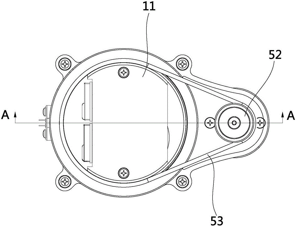
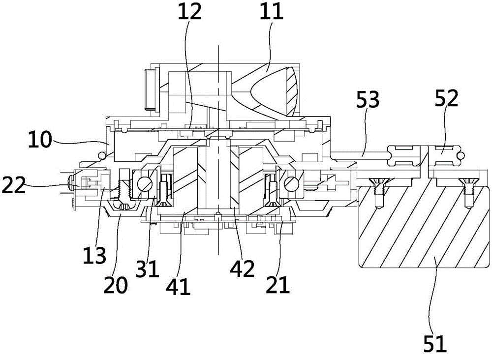
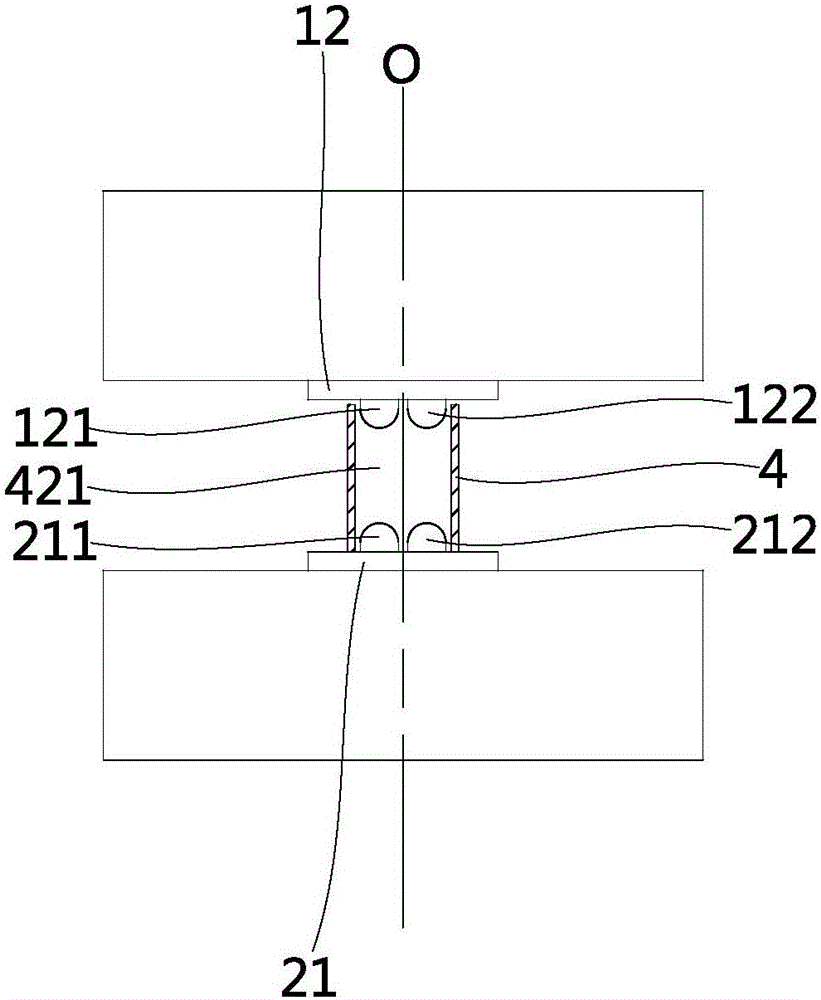
[0032] Such as Figures 1 to 3 , 5 and 6, the laser distance measuring device of the present invention includes a fixed assembly and a rotating assembly, the rotating assembly is rotatably connected to the fixed assembly, a driving mechanism is connected to the fixed assembly, and the driving mechanism drives the rotating assembly to rotate. Wherein the rotating assembly includes a laser ranging movement 11, an intermediate housing 10, a code disc 13 and an upper circuit board 12 installed at the bottom of the laser ranging movement 11, the upper circuit board 12 is electrically connected with the laser ranging movement 11, and the middle The upper end of the housing 10 is fixedly connected to the lower end of the laser ranging movement 11, the intermediate housing 10 and the code disc 13 are fixedly connected by a flange, and the outer ring of the bearing 31 is fixed on the intermediate housing 10 by screws. The driving mechanism includes a motor 51 , a pulley 52 and a belt 5...

Embodiment 2

[0040] Such as Figure 7 and 8 As shown, the difference between this embodiment and Embodiment 1 is that the drive mechanism in this embodiment includes a brushless motor 54, which has the characteristics of high working efficiency, high torque at low speed and high precision, and the brushless motor 54 The output shaft of the laser is connected to the rotating assembly through a transmission mechanism, the transmission mechanism can be a gear, a flange or a coupling, etc., and the brushless motor 54 is located in the installation cavity. Such a design can greatly reduce the volume of the entire laser distance measuring device. Simultaneously, the structure of the whole laser distance measuring device is also simplified.

[0041] The laser ranging device of the present invention is mainly applied to mobile robots and radars.


PUM


Abstract

The invention discloses a laser ranging device and belongs to the field of target detection recognition and information transmission. The technical problem that according to a laser ranging device in the prior art, mistakes and interference are likely to happen is solved. The laser ranging device comprises a fixed assembly and a rotary assembly provided with a laser ranging movement. The fixed assembly is connected with a driving mechanism used for driving the rotary assembly to rotate. The fixed assembly comprises a lower circuit board provided with a first signal receiving module. The rotary assembly comprises an upper circuit board which is provided with a first signal emission module, the upper circuit board is electrically connected with the laser ranging movement, the first signal emission module converts digital signals on the upper circuit board into optical signals and transmits the optical signals to the first signal receiving module, a conductive slide ring is connected between the lower circuit board and the upper circuit board, and the lower circuit board supplies power to the upper circuit board through the conductive slide ring.

Description

【Technical field】 [0001] The invention relates to the field of target detection and identification and information transmission, in particular to a laser distance measuring device. 【Background technique】 [0002] Laser ranging can measure the distance from an object to an observation point through triangulation ranging or TOF. It is currently widely used in navigation and obstacle avoidance of mobile robots and radars. Taking a mobile robot as an example, since a mobile robot needs to sense obstacles and the surrounding environment to determine its own position and plan a moving route during its movement, it generally needs to install multiple distance measuring devices to achieve the effect. Laser ranging has the advantages of non-contact, high precision, large ranging distance and fast speed. Existing laser ranging devices generally use two methods to realize the transmission of power and information between the fixed component and the rotating component. One is to use sl...

Claims


Application Information

Patent Timeline
Patent Type & Authority Applications(China)
IPC IPC(8): G01C3/00
CPCG01C3/00
Inventor 刘崇求余为财王越
Owner LANHAI PHOTOELECTRICITY TECH CO LTD
Why Eureka
Try Eureka