Visual micro-pore structure simulation physical model and manufacturing method thereof

A physical model and microscopic pore technology, applied in teaching models, educational tools, instruments, etc., can solve the problems of high production cost, low success rate, complicated production methods, etc., and achieve the effect of easy observation, high success rate and strong visualization

Inactive Publication Date: 2016-08-17
UNIV OF SCI & TECH BEIJING
View PDF7 Cites 27 Cited by
  • Summary
  • Abstract
  • Description
  • Claims
  • Application Information

AI Technical Summary

Problems solved by technology

However, for a long time, the research on the seepage problem in the microscopic model mainly includes: ① Taking artificial core or artificial geological model as the research object, the cost is low, the processing is relatively simple, but the error is large, and the flow of oil, gas, water and other fluids cannot be observed. The driving process cannot meet the needs of current oilfield development; ②The existing porous media models, such as microcapillary network models, quartz sand interlayer models, simulated pore structure models, and models using real cores as the main body, are transparent and can simulate displacement The process is visible, and images can be collected and analyzed, but the production methods are complicated, the production cost is high, the production accuracy is poor, and the size of the pore network structure is uncontrollable; ③ For the existing porous media model made of epoxy resin bonding, the production The resulting model has good transparency, strong visibility, and can clearly observe the microscopic seepage process in the model, but the model has poor manufacturing accuracy, uncontrollable size, poor bonding ability, no pressure resistance, low success rate, and cannot reach low\ The micron-scale pore size requirements of ultra-low permeability oilfields cannot meet the research on microscopic parameters of reservoirs

Method used


Image

  • Visual micro-pore structure simulation physical model and manufacturing method thereof
  • Visual micro-pore structure simulation physical model and manufacturing method thereof
  • Visual micro-pore structure simulation physical model and manufacturing method thereof

Examples


Embodiment 1

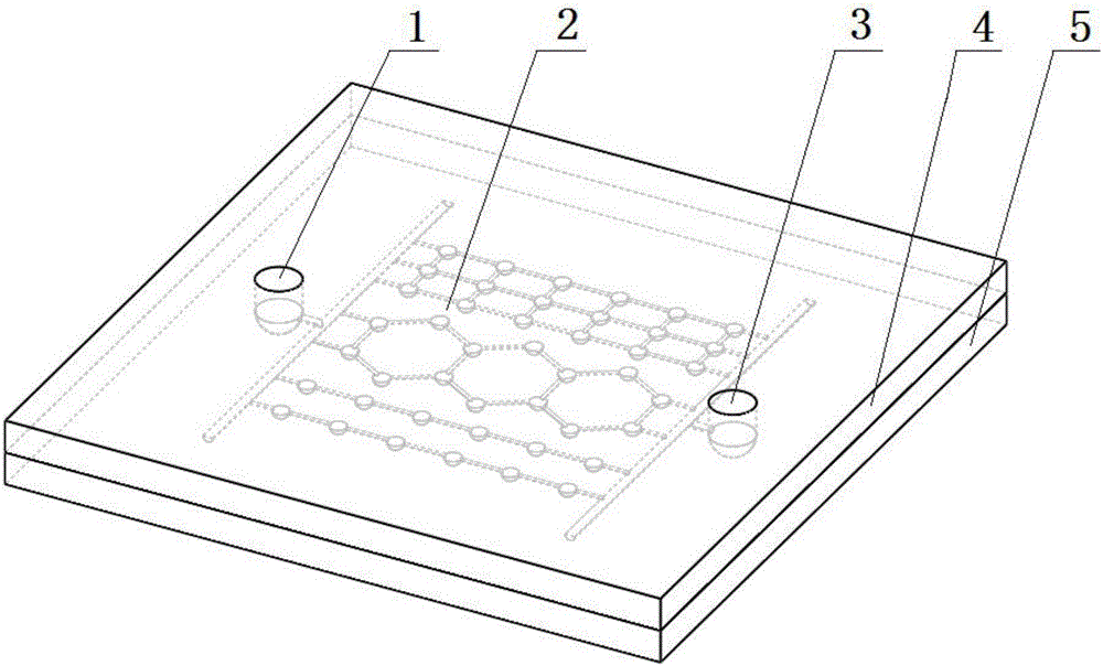
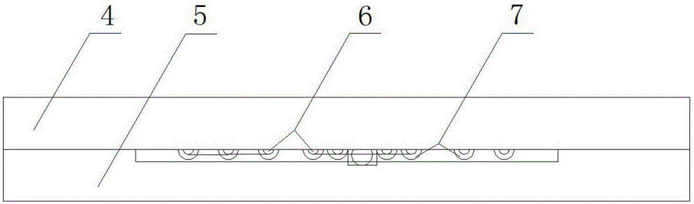
[0045] Such as figure 1 and figure 2 and 3 As shown, a visual microscopic pore structure simulation physical model includes a main board 5 and an attached board 4, wherein the main board 5 is formed by mixing epoxy resin and curing agent, and the attached board 4 is processed by a flat optical glass plate. The attached plate 4 includes an injection port 1 and a production port 3, the main board 5 includes a pore network structure 2, and the pore network structure 2 includes the following three parts:

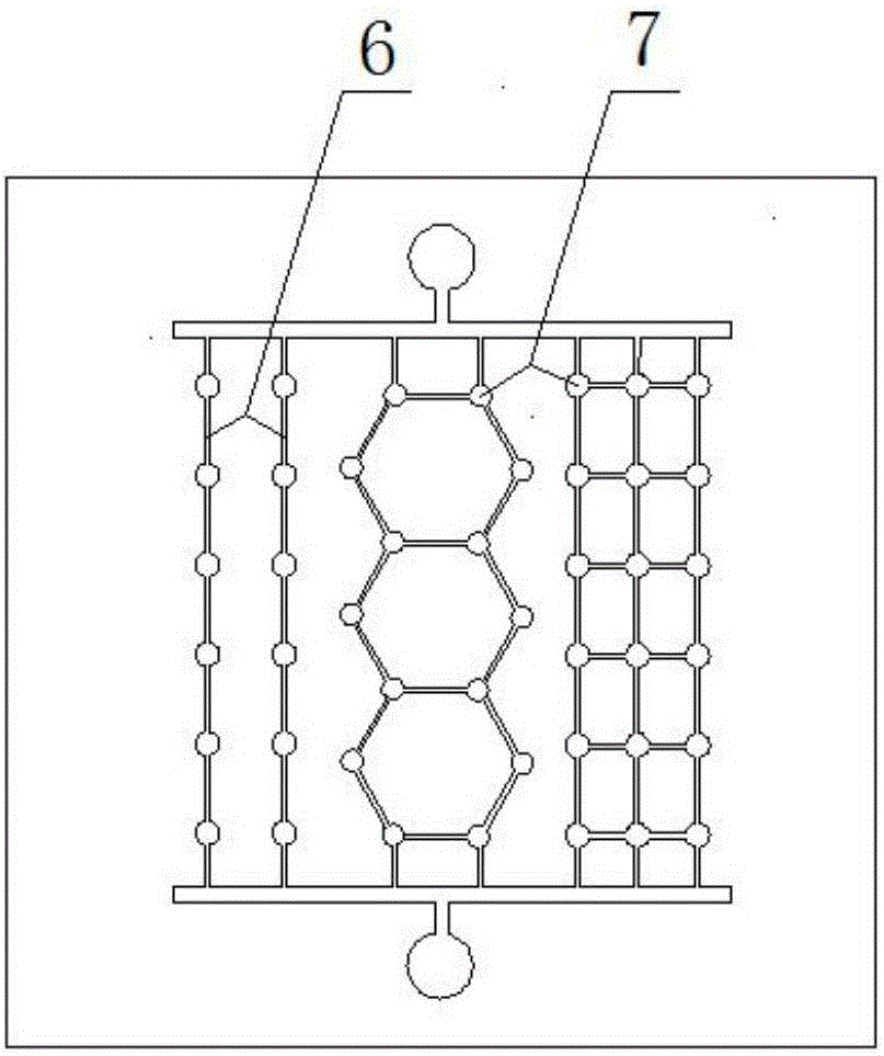
[0046] The first part of the pore network structure includes two throats 6 extending in parallel from the injection port 1 to the production port 3, and holes 7 are arranged on the two throats;

[0047] The second part of the pore network structure includes two or more hexagonal throats 6 extending end-to-end from the injection port 1 to the production port 3, and holes 7 are arranged on the vertices of the hexagonal throats;

[0048] The third part of the pore network structu...

Embodiment 2

[0063] The difference between this embodiment and Embodiment 1 is that a method for making a physical simulation model of a visualized microscopic pore structure includes the following steps:

[0064] (1) Design of pore network structure in the model: According to the casting thin section and mercury intrusion data of actual low and / or ultra-low permeability reservoir rock samples, the reservoir parameters are obtained, including the coordination number (referring to a pore connecting throat number of channels), pore-throat ratio, and throat radius, and draw the pore network structure corresponding to the reservoir parameters; among them, use the software to draw the pores with the same throat radius and pore-throat ratio, but different coordination numbers Network structure; preferably Auto CAD drawing software; in the present embodiment, it is determined that the throat radius is 10-30um, preferably 20um, the pore-throat ratio is 3-6, preferably 4, and the coordination number...

Embodiment 3

[0074] The difference between this embodiment and Embodiment 1 is that a method for making a physical simulation model of a visualized microscopic pore structure includes the following steps:

[0075] Using the simulated physical model obtained by the above preparation to carry out microcosmic oil displacement experiments with different coordination numbers, the experimental equipment is as follows Figure 4 As shown, the visualized microscopic equipment is connected by a video recorder 11 and an image display 12, and the above-mentioned simulated physical model 10 is placed under the video recorder 11, and the injection port of the model is connected to a drive system composed of a displacement pump 8 and an intermediate container 9. For the system, the simulation physical model 10 outlet is connected to the fluid recovery bottle, and the microscopic displacement experiment can be carried out. Use this equipment to observe the fluid displacement status of different coordinati...


PUM


Abstract

The invention mainly belongs to the technical field of oil and gas field microcosmic mechanism research and particularly relates to a visual micro-pore structure simulation physical model and a manufacturing method thereof. The simulation physical model comprises a primary board and a secondary board. The secondary board comprises an injection port and a recovery port. The primary board is formed by mixing epoxy resin and a curing agent. The secondary board is formed by processing planar optical glass. The primary board comprises a pore network structure which is composed of three parts. The front ends of the three parts of the pore network structure are connected with the injection port through a common throat, and the tail ends of the three parts of the pore network structures are connected with the recovery port through a common throat. By means of the method, the throat diameter, any throat-to-pore ratio and various coordination numbers under micrometer size can be achieved, and the manufactured physical model is good in transparency, high in visualization and low in manufacturing cost.

Description

technical field [0001] The invention mainly belongs to the technical field of oil and gas field microcosmic mechanism research, and in particular relates to a visualized microcosmic pore structure simulation physical model and a manufacturing method. Background technique [0002] In recent years, due to the rapid development of medium- and high-permeability oilfields and the slowdown in the increase in proven reserves, the oil production of low-permeability and ultra-low-permeability reservoirs will become more and more important in reservoir engineering, and the development of low-permeability reservoirs will have important strategic significance. Therefore, the study of fluid seepage in porous media is of great significance for the development of underground fluid resources such as oil and gas, surface engineering and anti-seepage of river dams. However, for a long time, the research on the seepage problem in the microscopic model mainly includes: ① Taking artificial core...

Claims


Application Information

Patent Timeline
Patent Type & Authority Applications(China)
IPC IPC(8): G09B23/40
CPCG09B23/40
Inventor 朱维耀李兵兵刘雅静宋智勇岳明刘静文范盼伟
Owner UNIV OF SCI & TECH BEIJING
Why Eureka
Try Eureka