A high-pixel infrared focal plane detector and its preparation method
A high-pixel and detector technology, applied in the field of infrared focal plane detection, can solve problems such as uneven surface of epitaxial wafers, and achieve the effects of avoiding cracks or damage, avoiding the introduction of stress, and uniform force.
- Summary
- Abstract
- Description
- Claims
- Application Information
AI Technical Summary
Problems solved by technology
Method used
Image
Examples
Embodiment 1
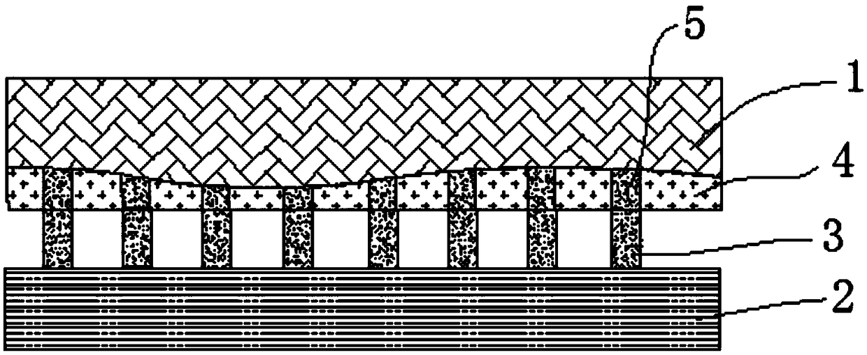
[0027] figure 1 A high-pixel infrared focal plane detector is shown, which includes interconnected mercury cadmium telluride epitaxial wafers 1 and a readout circuit 2, and the surface of the readout circuit 2 is prepared with a first flip-chip welding structure 3, cadmium telluride The surface of the mercury epitaxial wafer 1 is prepared with a second flip chip structure 5 matching the first flip chip structure 3, wherein the surface of the mercury cadmium telluride epitaxial wafer 1 is also covered with a layer of protective material 4, and the protective material 4 can be filled with glue or ZnS etc. cover the HgCdTe epitaxial wafer 1 with the second flip-chip bonding structure 5 exposed on the surface of the HgCdTe epitaxial wafer 1, and the readout circuit 2 and the HgCdTe epitaxial wafer 1 pass through the first flip-chip bonding structure 3 and the second flip chip structure 5 are connected.
Embodiment 2
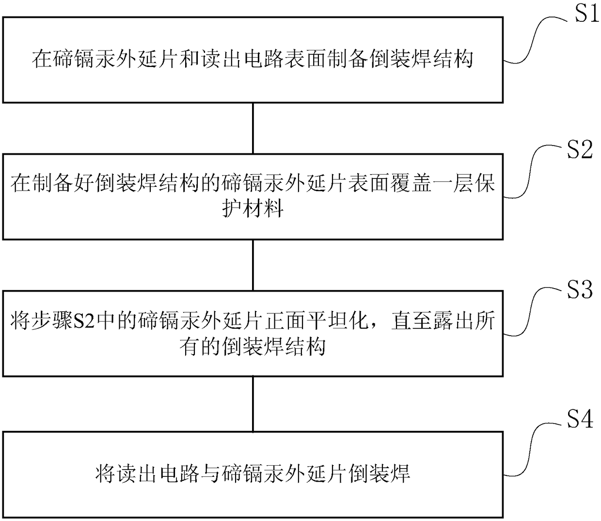
[0029] In this embodiment, a preparation method of a high-pixel infrared focal plane detector is also proposed, which is used to make the infrared focal plane detector in the embodiment, such as figure 2 shown, including the following steps:
[0030] S1. Prepare a flip-chip structure on the surface of the HgCdTe epitaxial wafer and the readout circuit;
[0031] S2. Covering a layer of protective material on the surface of the HgCdTe epitaxial wafer with the flip chip structure prepared;
[0032] S3, planarizing the front side of the HgCdTe epitaxial wafer in step S2 until all the flip chip structures are exposed;
[0033] S4. Flip-chip welding the readout circuit to the HgCdTe epitaxial wafer.
[0034] Specifically, according to the existing process technology, namely photolithography, coating and stripping, the second flip chip structure 5 is prepared on the HgCdTe epitaxial wafer 1 (such as image 3 As shown), the first flip-chip structure 3 is prepared on the readout ci...
Embodiment 3
[0036] In this implementation, steps are also included:
[0037] S1. Prepare a flip-chip structure on the surface of the HgCdTe epitaxial wafer and the readout circuit;
[0038] S2. Covering a layer of protective material on the surface of the HgCdTe epitaxial wafer with the flip chip structure prepared;
[0039] S3, planarizing the front side of the HgCdTe epitaxial wafer in step S2 until all the flip chip structures are exposed;
[0040] S4. Flip-chip welding the readout circuit to the HgCdTe epitaxial wafer.
[0041] Specifically, according to the existing technology, that is, photolithography, coating and stripping, the second flip-chip structure 5 is prepared on the HgCdTe epitaxial wafer 1, and the second flip-chip structure is prepared on the readout circuit 2 3. Then, a layer of ZnS with a thickness not lower than the second flip-chip structure is deposited on the surface of the HgCdTe epitaxial wafer 1 by means of electron beam evaporation to obtain the HgCdTe epit...
PUM
 Abstract
Description
Claims
Application Information
 - R&D
- Intellectual Property
- Life Sciences
- Materials
- Tech Scout
- Unparalleled Data Quality
- Higher Quality Content
- 60% Fewer Hallucinations
Browse by: Latest US Patents, China's latest patents, Technical Efficacy Thesaurus, Application Domain, Technology Topic, Popular Technical Reports.
© 2025 PatSnap. All rights reserved.Legal|Privacy policy|Modern Slavery Act Transparency Statement|Sitemap|About US| Contact US: help@patsnap.com


