Improved diffusion technology of polycrystalline solar cell

A solar cell and diffusion process technology, applied in the field of solar cells, can solve the problems of low conversion efficiency of solar cells, and achieve the effects of high conversion efficiency, low packaging loss and high conversion rate

Active Publication Date: 2016-08-17
ZHEJIANG GUANGLONG ENERGY TECH
View PDF4 Cites 1 Cited by
  • Summary
  • Abstract
  • Description
  • Claims
  • Application Information

AI Technical Summary

Problems solved by technology

[0003] In the actual production process, the conversion efficiency of solar cells using the one-step diffusion method in the prior art is generally low

Method used


Image

  • Improved diffusion technology of polycrystalline solar cell
  • Improved diffusion technology of polycrystalline solar cell
  • Improved diffusion technology of polycrystalline solar cell

Examples


Embodiment 1

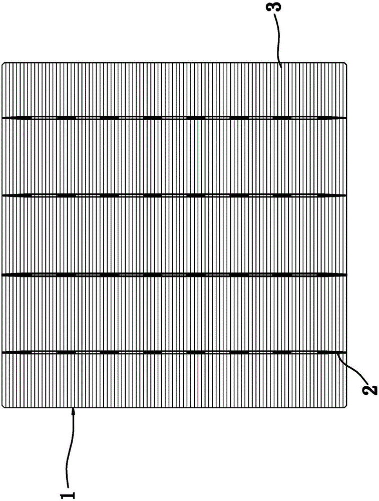
[0033] Such as figure 1 As shown, the polycrystalline solar cell includes a plate-shaped body 1, one side of the body 1 is a positive electrode, the other side of the body 1 is a negative electrode, and four main grids 2 and 90 fine grids are evenly distributed on the positive electrode. 3. The main grid 2 and the fine grid 3 are vertically arranged and they are electrically connected. The distance between each main grid 2 is 35 mm, the width of the main grid 2 is 0.8 mm, and the spacing of the fine grid 3 is 1.4 mm. The width is 0.035 mm.

[0034] Such as figure 1 As shown, the main grid 2 is arranged longitudinally and uniformly by several main grid segments; the length of each main grid segment is 7 mm; the length of the fine grid 3 is 152 mm.

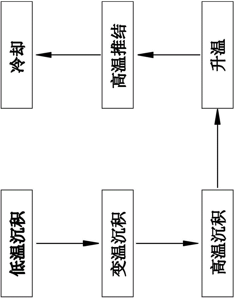
[0035] Such as figure 2 Shown, the diffusion process of this improved polycrystalline solar cell, this process comprises the following steps:

[0036] A. Low-temperature deposition: Put the body into an ordinary diffusion furna...

Embodiment 2

[0048] Such as figure 1 As shown, the polycrystalline solar cell includes a plate-shaped body 1, one side of the body 1 is a positive electrode, the other side of the body 1 is a negative electrode, and four main grids 2 and 90 fine grids are evenly distributed on the positive electrode. 3. The main grid 2 and the fine grid 3 are vertically arranged and they are electrically connected. The distance between each main grid 2 is 42 mm, the width of the main grid 2 is 1.2 mm, and the spacing of the fine grid 3 is 2.0 mm. The width is 0.045 mm.

[0049] Such as figure 1 As shown, the main grid 2 is arranged longitudinally and uniformly by several main grid segments; the length of each main grid segment is 11 mm; the length of the fine grid 3 is 158 mm.

[0050] Such as figure 2 Shown, the diffusion process of this improved polycrystalline solar cell, this process comprises the following steps:

[0051] A. Low-temperature deposition: Put the body into an ordinary diffusion furn...

Embodiment 3

[0062] Such as figure 1 As shown, the polycrystalline solar cell includes a plate-shaped body 1, one side of the body 1 is a positive electrode, the other side of the body 1 is a negative electrode, and four main grids 2 and 90 fine grids are evenly distributed on the positive electrode. 3. The main grid 2 and the fine grid 3 are vertically arranged and they are electrically connected. The distance between each main grid 2 is 38 mm, the width of the main grid 2 is 1.0 mm, and the spacing of the fine grid 3 is 1.7 mm. The width is 0.04 mm.

[0063] Such as figure 1 As shown, the main grid 2 is arranged longitudinally and uniformly by several main grid segments; the length of each main grid segment is 9 mm; the length of the fine grid 3 is 155 mm.

[0064] Such as figure 2 Shown, the diffusion process of this improved polycrystalline solar cell, this process comprises the following steps:

[0065] A. Low-temperature deposition: Put the body into an ordinary diffusion furnac...


PUM


Abstract

The invention provides an improved diffusion technology of a polycrystalline solar cell, belongs to the technical field of solar cells and solves the technical problems of generally lower solar cell conversion efficiency with the adoption of a one-step diffusion method and the like in the prior art. The improved diffusion technology of the polycrystalline solar cell comprises steps as follows: A, low-temperature deposition; B, variable-temperature deposition; C, high-temperature deposition; D, warming; E, high-temperature diffusion; F, cooling. The polycrystalline solar cell prepared with the technology has the advantages of low encapsulating loss and high cell conversion ratio.

Description

technical field [0001] The invention belongs to the technical field of solar cells and relates to an improved diffusion process of polycrystalline solar cells. Background technique [0002] The production process of traditional polycrystalline solar cells mainly includes: texturing, diffusion, wet etching, PE coating, drying, printing back field, drying, printing back electrode, printing positive electrode, sintering and test sorting. The diffusion process directly affects the open circuit voltage of polycrystalline solar cells. The main influencing factor is the doping concentration on the surface of the diffusion. High doping concentration on the surface will cause heavy doping effect. The heavy doping effect will cause the narrowing of the forbidden band width, affect the intrinsic carrier concentration, affect the effective doping concentration and reduce the minority carrier lifetime. In silicon crystals, heavy doping can cause changes in the energy band structure, for...

Claims


Application Information

Patent Timeline
Patent Type & Authority Applications(China)
IPC IPC(8): H01L31/0224H01L31/18H01L21/223
CPCH01L21/223H01L31/022425H01L31/18H01L31/1804Y02E10/547Y02P70/50
Inventor 朱金浩蒋剑波王猛许布万光耀陈珏荣高非朱庆庆
Owner ZHEJIANG GUANGLONG ENERGY TECH
Why Eureka
Try Eureka