
Ion acceleration tube

A technology of accelerating tubes and ions, applied in nuclear technology and application fields, can solve the problems of lack of simple structure and low beam intensity

Inactive Publication Date: 2016-08-17
INST OF NUCLEAR PHYSICS & CHEM CHINA ACADEMY OF
View PDF7 Cites 6 Cited by
  • Summary
  • Abstract
  • Description
  • Claims
  • Application Information

AI Technical Summary

Problems solved by technology

"my country's High-voltage Accelerator Technology and Application Progress" (2004, the Seventh National Member Congress and Academic Report of the Particle Accelerator Society) disclosed high-voltage electrostatic ion accelerators with a terminal voltage exceeding 5MV, but the beam intensity is not high, at 300uA within
[0003] At present, there is a lack of high-voltage electrostatic ion accelerator tubes with a simple structure that can be used for terminal voltages exceeding 5MV and beam intensity exceeding 1mA.

Method used


Image

  • Ion acceleration tube

Examples


Embodiment 1

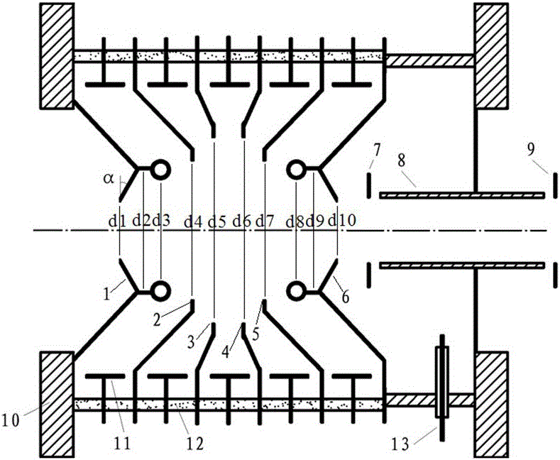
[0030] The ion beam to be accelerated is a deuterium ion beam, the beam intensity is 1mA, the voltage at both ends of each accelerating tube module is 250kV, the length is 200mm, the average acceleration gradient is 1.25MV / m, the ceramic insulating ring is 13, and the external working environment is 0.6MPa High pressure SF 6 For gas, the apertures of the entrance focusing accelerating electrode I1 and the exit defocusing accelerating electrode II6 are 30 mm, the apertures of the entrance accelerating focusing electrode II2 and the exit defocusing accelerating electrode I5 are 50 mm, the apertures of the intermediate accelerating electrode I3 and the intermediate accelerating electrode II4 are 70 mm, The length of the drift tube 8 is 80 mm, and the potential of the stop electrode 7 and the stop electrode 9 is the same, which is 2 kV lower than that of the drift tube 8 . 20 identical ion accelerating tube modules are assembled together to form an ultra-high-voltage strong-curren...

Embodiment 2

[0032]The ion beam to be accelerated is a proton beam, the beam intensity is 2mA, the voltage across each accelerating tube is 225kV, the length is 200mm, the average acceleration gradient is 1.125MV / m, the ceramic insulating ring is 13, and the external working environment is a high-voltage SF of 0.6MPa 6 For gas, the apertures of the entrance focusing accelerating electrode I1 and the exit defocusing accelerating electrode II6 are 30 mm, the apertures of the entrance accelerating focusing electrode II2 and the exit defocusing accelerating electrode I5 are 50 mm, the apertures of the intermediate accelerating electrode I3 and the intermediate accelerating electrode II4 are 70 mm, The length of the drift tube 8 is 80 mm, and the potential of the stop electrode 7 and the stop electrode 9 is the same, which is 2 kV lower than that of the drift tube 8 . 36 sections of the same accelerating tubes are assembled together to form a proton beam with a length of 7.2 meters, a total acce...


PUM


Abstract

The invention provides an ion acceleration tube, which is used for a static electricity high-voltage ion accelerator. The ion acceleration tube adopts modularized structural design; the acceleration voltage of each ion acceleration tube module is about 250kV; a certain number of ion acceleration modules are connected in series; the required ultra-high acceleration voltage can be obtained. The ion acceleration tube module comprises a strong focusing acceleration region and a space charge neutralization region, and is used for eliminating the self space charge effect of ion beams; the accelerated transmission of ion beams exceeding 1mA can be realized. Meanwhile, the ion acceleration tube module is also provided with a secondary electronic strong inhibition structure; when an ultra-high voltage acceleration system exceeding 5MV end voltage is formed, the occurrence of full voltage effect can be effectively prevented. The ion acceleration tube provided by the invention has the advantage that the ion beams with the end voltage exceeding 5MV and the beam current intensity exceeding 1mA can be obtained. The ion acceleration tube is suitable to be applied in the fields of ion injection, ion beam tumor treatment, nucleopore membrane production, neutron radiography and the like.

Description

technical field [0001] The invention belongs to the field of nuclear technology and application, and in particular relates to an ion accelerating tube. Background technique [0002] High-energy high-current ion beams have very broad application prospects in material modification, tumor treatment and physical experiments. At present, one way is to use radio frequency ion accelerators, which can provide high-current ion beams with energy exceeding 3MeV and beam intensity exceeding 1mA However, the technical difficulty is high, and the energy of the ion beam generated is large; another way is to use a high-voltage electrostatic ion accelerator, which has a small ion beam energy dispersion, high energy conversion efficiency of the whole machine, and low operating costs, which are suitable for commercial applications. , However, when the beam current intensity exceeds 1mA, the terminal voltage is relatively low, below 1MV. "Physical Design of 400 kV High-Current Neutron Generato...

Claims


Application Information

Patent Timeline
Patent Type & Authority Applications(China)
IPC IPC(8): H05H1/54
CPCH05H1/54
Inventor 李彦何小海李小飞娄本超唐君薛小明牟云峰胡永宏
Owner INST OF NUCLEAR PHYSICS & CHEM CHINA ACADEMY OF
Learn More