Optical fiber drawing technology

A wire drawing and process technology, applied in the direction of manufacturing tools, glass manufacturing equipment, etc., can solve the problems affecting the cooling effect of helium gas, and achieve the effects of improving the cooling effect of helium gas, the structure is simple, and the heat conduction efficiency is improved

Active Publication Date: 2016-08-24
HANGZHOU FUTONG COMM TECH CO LTD
View PDF4 Cites 3 Cited by
  • Summary
  • Abstract
  • Description
  • Claims
  • Application Information

AI Technical Summary

Problems solved by technology

[0016] The invention provides an optical fiber drawing process, which solves the defect that the existing optical fiber drawing process has a thick laminar bottom layer in the drawing cooling process and affects the cooling effect of helium

Method used


Image

  • Optical fiber drawing technology
  • Optical fiber drawing technology
  • Optical fiber drawing technology

Examples


Embodiment 1

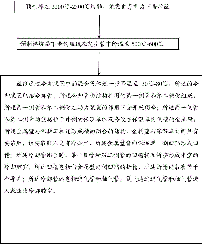
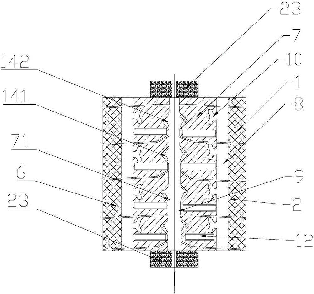
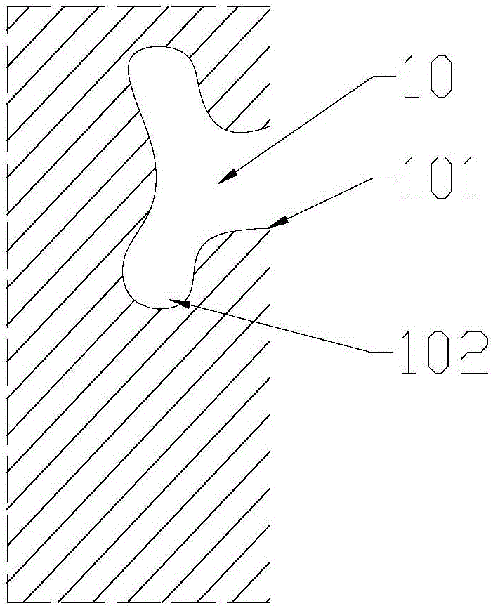
[0050] Embodiment 1: The embodiment of the present invention provides a cooling device 1 (see attached figure 2 , 3 , 4, 5, 6, 7), applied to step 3), the cooling device 1 cooling device includes a cooling pipe 2, and the cooling pipe is composed of a first side pipe 3 and a second side pipe 4 with the same structure , the first side pipe 3 and the second side pipe 4 are vertically separated or closed under the action of the power unit 5; On the metal wall 7 on the inner wall of the heat preservation cover 6, the metal wall 7 is connected with the protective cover 6 to form a horizontally closed structure. There is an installation cavity 8 between the metal wall 7 and the heat preservation cover 6, and the installation cavity 8 is filled with cooling water. The side of the metal wall 7 facing away from the insulation cover 6 is recessed to form a groove 71; when the cooling pipe 2 is closed, the grooves 71 of the first side pipe 3 and the second side pipe 4 are spliced ​​tog...

Embodiment 2

[0054] Embodiment 2: The temperature of the helium is 15°C. A drying device is installed at both ends of the cooling chamber. The drying device is equipped with a desiccant to effectively reduce the moisture in the cooling chamber. Under the condition that the temperature of the helium is controlled at 5°C-15°C, the condensation of the cooling water to The impact on the physical properties of the fiber on the fiber.

[0055] During the implementation of the embodiment of the present invention, helium gas at 5°C-15°C enters the cooling chamber through the intake pipe, and under the action of the groove and its folded grooves and guide vanes, a turbulent flow is formed to destroy the optical fiber and bring it into the bottom layer of the air laminar flow, Helium is drawn out of the cooling chamber through the extraction tube. The drying device dries the air entering the cooling chamber to reduce the moisture entering the cooling chamber. The hot helium in the cooling chamber ...


PUM

PropertyMeasurementUnit
diameteraaaaaaaaaa

Abstract

The invention discloses an optical fiber drawing technology. The optical fiber drawing technology comprises steps as follows: 1), a melt drawing process: a preform rod is molten at the temperature of 2,200-2,300 DEG C, droops and is drawn by means of own gravity; 2), a shaping cooling process: drooping wires formed after melting of the preform rod are cooled to 500-600 DEG C in a shaping tube; 3), drawn wire cooling process: the wires are further cooled to 30-80 DEG C under the action of helium in a cooling device, and the cooling device in the step 3) comprises a cooling tube, the cooling tube comprises a first side tube and a second side tube with the same structure, a mounting cavity is formed between each metal wall and a corresponding heat insulation cover, and one side, opposite to the heat insulation cover, of the metal wall is recessed to form a groove; the grooves of the pair of side tubes are spliced to form a cooling cavity, each groove comprises a folding slot, and guide vanes are arranged in the folding slot. According to the optical fiber drawing technology, the cooling cavity formed by the grooves, the folding slots, the guide vanes and the like is arranged, turbulence is increased, the thickness of a laminar sublayer formed by downward movement of the optical fiber wires is effectively reduced, and a helium cooling effect is further improved.

Description

technical field [0001] The invention relates to the field of optical fiber production, in particular to an optical fiber drawing process. Background technique [0002] Optical fiber, short for optical fiber, is a fiber made of glass or plastic that acts as a means of light transmission. The optical fiber is composed of two layers of glass with different refractive indices. The inner layer is the optical core with a diameter of several microns to tens of microns, and the outer layer has a diameter of 0.1 to 0.2 mm. Generally, the refractive index of the inner core glass is 1% larger than that of the outer glass. According to the principle of refraction and total reflection of light, when the angle at which the light hits the interface between the inner core and the outer layer is greater than the critical angle for total reflection, the light cannot pass through the interface and is fully reflected. At present, the optical fiber used in communication is generally silica opt...

Claims


Application Information

Patent Timeline
Patent Type & Authority Applications(China)
IPC IPC(8): C03B37/025C03B37/027
CPCC03B37/025C03B37/027C03B37/02718C03B37/032
Inventor 张立永王醒东
Owner HANGZHOU FUTONG COMM TECH CO LTD
Why Eureka
Try Eureka