Method for machining narrow groove system impeller, grinding head and preparation method of grinding head

A grinding head and impeller technology, applied in the field of CNC machining, can solve the problems of reducing the precision of the machined surface, burning the machined surface, and aggravating tool wear, so as to reduce adhesion and wear, improve the quality of the machined surface, and reduce the amount of machining wear Effect

Active Publication Date: 2016-08-31
NORTHEASTERN UNIV
View PDF8 Cites 16 Cited by
  • Summary
  • Abstract
  • Description
  • Claims
  • Application Information

AI Technical Summary

Problems solved by technology

[0003] The traditional grinding process mainly uses the grinding wheel to process the surface of the workpiece, but for the workpiece with a complex and narrow groove system (the groove width is generally less than 20 ~ 30mm), due to the relationship between the size, the traditional grinding wheel is difficult to process, and can only use Small diameter grinding head to process it
However, the traditional grinding head often has a large grinding force and high grinding temperature during processing, which not only causes burns on the processed surface, but also easily causes chips to stick to the surface of the workpiece and the grinding head, which not only increases tool wear, but also Reduced accuracy of machined surfaces
[0004] In addition, due to the thin-walled surface of the impeller is thin and easy to deform, if the process parameters are selected unreasonably, vibration marks will often be left on the surface of the workpiece, resulting in low surface quality.

Method used


Image

  • Method for machining narrow groove system impeller, grinding head and preparation method of grinding head
  • Method for machining narrow groove system impeller, grinding head and preparation method of grinding head
  • Method for machining narrow groove system impeller, grinding head and preparation method of grinding head

Examples


Embodiment Construction

[0050]The specific implementation manners of the present invention will be described in detail below in conjunction with the accompanying drawings.

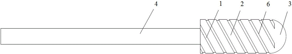
[0051] One embodiment of the present invention provides a grinding head for processing narrow grooved impellers, such as figure 1 As shown, the grinding head 2 is a cylinder, the top 3 of the grinding head 1 is spherical, and the side wall of the grinding head 2 is provided with a spiral groove 1 . The grinding head 2 is bonded on the handle 4, and the grooved part has a groove edge 6.

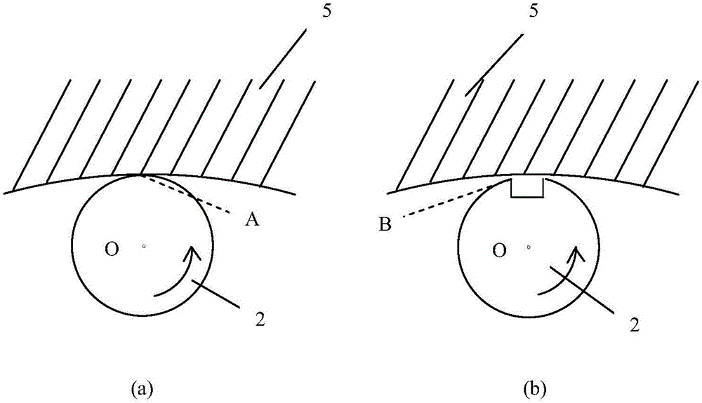
[0052] Schematic diagram of grinding head processing figure 2 As shown, the surface of the grinding head 2 is a cylindrical surface, and the section perpendicular to the axis is a circle, and the distance from the center of the circle to the processed surface is OA. After slotting at point A, the distance from the center of the circle to the machined surface is still OA. When the grinding head 2 rotates to the figure 2 (a) When the angles o...


PUM

PropertyMeasurementUnit
angleaaaaaaaaaa

Abstract

The invention provides a method for machining a narrow groove system impeller, a grinding head and a preparation method of the grinding head. The grinding head is a cylinder. The top end of the grinding head is in the shape of a spherical surface, and a spiral groove is formed in the side wall of the grinding head. The preparation method includes the steps that materials for use are calculated; ingredients are weighed; wetting and material mixing are performed; pressing of grinding head sand blocks is performed; drying is performed; the firing link is performed; and the grinding head sand blocks which are qualified through checking are selected and enter an adhesion processing procedure of a cutter handle, the cutter handle is bonded, after adhesives are cured and stabilized, laser dressing is performed, grooving is performed, and acceptance check of the grinding head is performed, and therefore preparation of the grinding head is completed. The method for machining the narrow groove system impeller through the grinding head includes the steps that fluttering stability analysis is performed, and a stable lobe graph of a grinding system is established; the technological parameter selecting range of stable grinding is determined; and technological parameters of stable grinding are selected, and the grinding head is installed for grinding machining. By means of the grinding head, the grinding temperature is effectively lowered, the adhesion and abrasion effects of cuttings on the grinding head are reduced, the machining surface burning problem is reduced, and better machining surface quality is acquired.

Description

technical field [0001] The invention relates to the technical field of numerical control machining, in particular to a method for machining an impeller with a narrow groove system, a grinding head and a preparation method thereof. Background technique [0002] With the advancement of science and technology, people have higher and higher requirements for the precision of products. Improving the surface quality of the impeller, which is a crucial part in automobile engines and aero-engines, is an important problem that needs to be solved urgently. [0003] The traditional grinding process mainly uses the grinding wheel to process the surface of the workpiece, but for the workpiece with a complex and narrow groove system (the groove width is generally less than 20 ~ 30mm), due to the relationship between the size, the traditional grinding wheel is difficult to process, and can only use Small diameter grinding head to process it. However, the traditional grinding head often has...

Claims


Application Information

Patent Timeline
Patent Type & Authority Applications(China)
IPC IPC(8): B24B1/00B24B19/14B24D3/14B24D7/18B24D18/00
CPCB24B1/00B24B19/14B24D3/14B24D7/18B24D18/0009
Inventor 朱立达李兆斌张景强温泉于天彪巩亚东王宛山
Owner NORTHEASTERN UNIV
Why Eureka
Try Eureka