Subsurface tunnel drainage treatment method

A technology of tunnel drainage and treatment method, applied in drainage, tunnel, tunnel lining and other directions, can solve the problems of consuming man-hours, a large number of templates, and the drainage effect is not easy to achieve the expected effect, so as to facilitate later construction, ensure smoothness, and improve efflux The effect of efficiency

Inactive Publication Date: 2016-08-31
CHINA MCC5 GROUP CORP
View PDF5 Cites 4 Cited by
  • Summary
  • Abstract
  • Description
  • Claims
  • Application Information

AI Technical Summary

Problems solved by technology

Due to the long length of the drainage ditch of the tunnel, when the above-mentioned implementation method is adopted, a large number of formwork and wooden beams

Method used


Image

  • Subsurface tunnel drainage treatment method

Examples


Example Embodiment

[0028] Example 1

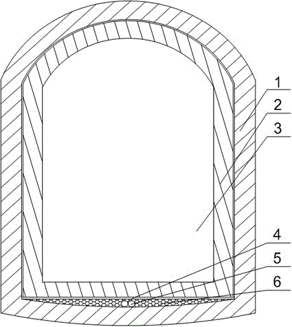
[0029] Such as figure 1 As shown, this embodiment includes the following steps in sequence:

[0030] a. Set up a number of dewatering wells in the middle of tunnel 3, and perform the first lining 1 construction after the water level in tunnel 3 drops to a safe position;

[0031] b. After the first lining 1 is completed, the silt on its bottom surface is removed, and then a water filter layer 6 is laid on the bottom of the first lining 1;

[0032] c. Multiple drainage pipes 5 extending to the sump of the shaft are laid in the water filter layer 6, and a valve is set at the end of the drainage pipe 5;

[0033] d. Lay a waterproof layer 4 on the upper surface of the water filter layer 6, and pour C25 concrete 2 on the waterproof layer 4.

[0034] The present embodiment abandons the method of setting dewatering wells at the bottom of the side walls on both sides of the tunnel 3. By setting dewatering wells in the middle of the tunnel 3, under the premise of ensuring that ...


PUM

PropertyMeasurementUnit
Thicknessaaaaaaaaaa
Thicknessaaaaaaaaaa

Abstract

The invention discloses a subsurface tunnel drainage treatment method. The method includes the following sequential steps that a, a plurality of precipitation wells are disposed in the middle of a tunnel firstly, and primary lining construction is performed after the water level in the tunnel descends to the safety position; b, after the primary lining construction is finished and silt on the bottom surface of a primary lining is removed, a water filtering layer is paved on the primary lining bottom surface; c, a plurality of drainage conduits extending to a vertical shaft water collection pit are laid in the water filtering layer; and d, a water-proof layer is paved on the upper surface of the water filtering layer, and C25 concrete is poured on the water-proof layer. During application, accumulated water remained on the primary lining is filtered through the water filtering layer and then enters the drainage conduits, and the accumulated water is drained into the vertical shaft water collection pit after being subjected to centralized treatment through the multiple drainage conduits; and in the drainage process, the water-proof layer and the concrete layer are disposed on the upper portion of the water filtering layer, so that the effect that the bottom surface of a secondary lining is kept dry is guaranteed, and later stage construction in the tunnel is facilitated.

Description

technical field [0001] The invention relates to the field of tunnel construction, in particular to a drainage treatment method for buried tunnels. Background technique [0002] After the tunnel is excavated, in order to stabilize the surrounding rock and ensure safe operation, it is necessary to build a layer of support structure with sufficient strength according to a certain outline size. This tunnel support structure is called tunnel lining. Commonly used lining types include in-situ pouring concrete, prefabricated block assembly, spray anchor or single shotcrete, and composite lining. For the geological structure with rich water content, composite lining is used in tunnel construction. Composite lining refers to the tunnel lining constructed in two layers, including the primary lining of the outer layer and the secondary lining of the inner layer. The secondary lining construction of the tunnel must keep the tunnel dry to ensure the safety and quality of the tunnel cons...

Claims


Application Information

Patent Timeline
IPC IPC(8): E21F16/02E21D11/10E21D11/38
CPCE21F16/02E21D11/10E21D11/383
Inventor 李攀李冬卿三贵
Owner CHINA MCC5 GROUP CORP
Why Eureka
Try Eureka