Preparation method for composite material antenna cover with thin-wall foam sandwich structure

A technology of composite materials and sandwich structures, applied in the direction of chemical instruments and methods, lamination, lamination devices, etc., can solve problems such as inability to process and difficult processing of thin-walled foam sandwiches

Active Publication Date: 2016-09-07
NAT UNIV OF DEFENSE TECH
View PDF4 Cites 18 Cited by
  • Summary
  • Abstract
  • Description
  • Claims
  • Application Information

AI Technical Summary

Problems solved by technology

[0011] The technical problem to be solved by the present invention is to solve the problem that the thin-wall foam sandwich core is difficult or impossible to process in the preparation process of the thin-wall foam sandwich structure radome, and to provide a preparation method for the thin-wall foam sandwich structure composite material radome,

Method used


Image

  • Preparation method for composite material antenna cover with thin-wall foam sandwich structure
  • Preparation method for composite material antenna cover with thin-wall foam sandwich structure
  • Preparation method for composite material antenna cover with thin-wall foam sandwich structure

Examples


Embodiment 1

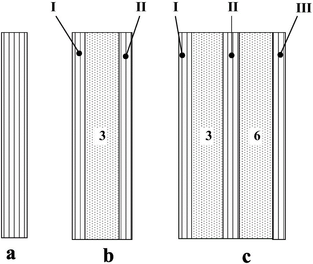
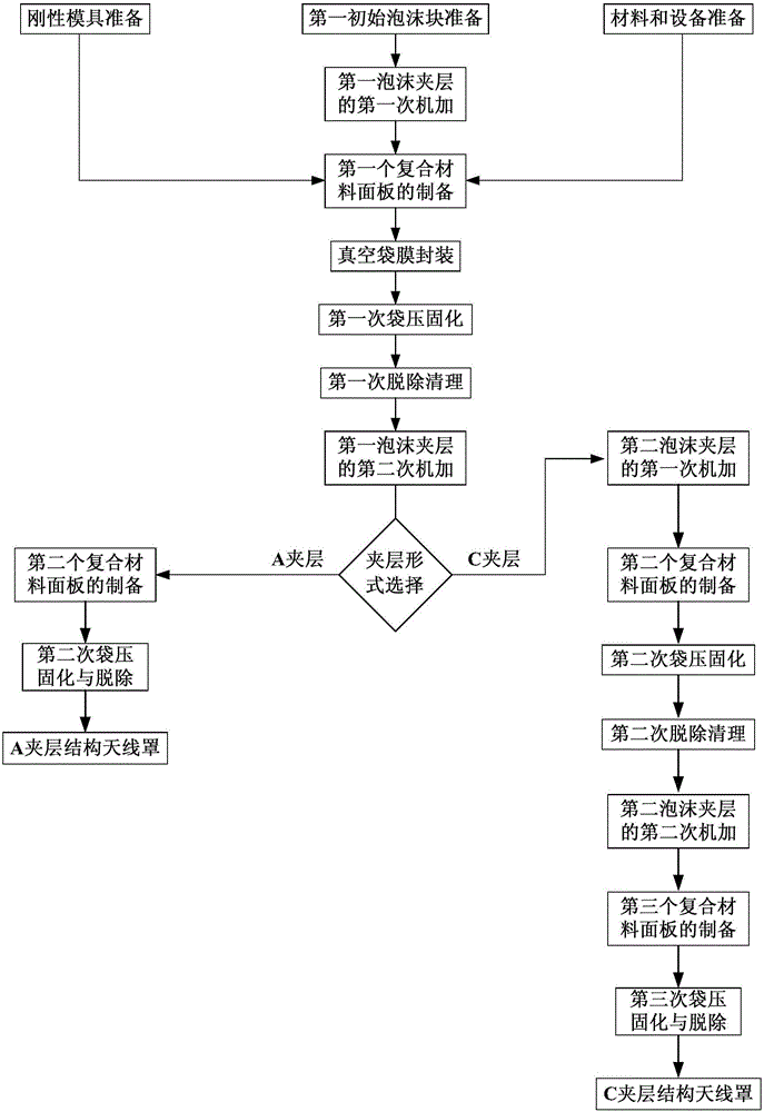
[0071] Example 1 Thin-wall foam A sandwich structure composite material radome with typical thickness 5mm

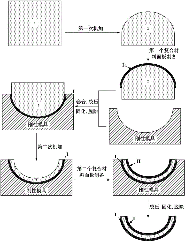
[0072] The first step, rigid mold preparation

[0073] Use 45 # The steel is processed to form the male mold for the radome product. The working surface of the male mold forms the corresponding internal cavity of the radome. The positioning and tool setting benchmarks of the foam interlayer are reserved on the base of the male mold for the second machining overtime.

[0074] Carry out surface grinding, cleaning and coating release agent treatment to male mold, set aside.

[0075] The second step, materials and equipment preparation

[0076] According to the technical requirements of the composite material radome, the S glass fiber fabric (reinforcing material) used for the composite material panel is cut into squares, and dried in an oven for later use; the impregnated liquid epoxy resin and curing agent are vacuum dehydrated and dried, spare. At the same time, pre...

Embodiment 2

[0099] Example 2 A typical thickness of 10mm, a thin-walled foam C sandwich structure radome with locally variable thickness

[0100] The first step, rigid mold preparation

[0101] Use 45 # The steel is processed to form the female mold for the radome product. The working surface of the concave cavity of the female mold corresponds to the outer wall structure of the formed radome. Positioning and tool setting references are reserved on the base of the female mold.

[0102] The molded female mold is surface polished, cleaned and coated with a release agent, and is ready for use.

[0103] The second step, materials and equipment preparation

[0104] According to the technical requirements of the composite radome, the quartz glass fiber fabric (reinforcing material) used for the composite panel is cut into pieces and dried in an oven for later use; the impregnated liquid vinyl resin and curing agent are vacuum dehydrated and dried for later use . At the same time, prepare ...


PUM

PropertyMeasurementUnit
thicknessaaaaaaaaaa

Abstract

The invention discloses a preparation method for a composite material antenna cover with a thin-wall foam sandwich structure. The invention aims to solve the problem of difficult processing or incapable processing for a thin-wall foam sandwich layer in the process of preparation of an antenna cover with a sandwich structure. According to a technical scheme of the invention, processing of the entire body of the thin-wall foam sandwich layer comprises two steps: performing primary processing, namely subjecting an initial foam block to single-face mechanical processing; and performing secondary processing after subjecting the single-face mechanically processed foam block to reinforcing and rigidity increasing, i.e., subjecting the rest of faces of the thin-wall sandwich layer to processing on a combination of a rigid mold, a composite material panel and the single-face mechanically processed foam block so as to prepare the thin-wall foam sandwich layer meeting the technical requirements of a target antenna cover. In addition, through resin impregnation with fabrics and a vacuum bag molding technique, preparation of the composite material panel and bonding of the panel with the foam sandwich layer in the target antenna cover are realized. By adopting the preparation method provided by the invention, the difficulty of preparation of the thin-wall foam sandwich layer through processing of the entire body of the initial foam block is overcome; the molding process of the antenna cover is simple; and the prepared antenna cover has the advantages of few defects, light weight and good wave permeability.

Description

technical field [0001] The invention relates to a molding method of a foam sandwich structure composite material, which belongs to the field of fiber-reinforced resin-based composite materials and processing. Background technique [0002] With the development of electronic communication and electronic countermeasure technology, radars, especially airborne radars, have higher and higher requirements on the weight reduction and wave-transmitting performance of radome. The structure of the radome wall ( figure 1 ) mainly have solid half-wave walls (single walls, such as figure 1 As shown in (a), A sandwich structure (skin-sandwich-skin, such as figure 1 (b) shown), C sandwich structure (skin-sandwich-skin-sandwich-skin, such as figure 1 (c) shown). Among them, the solid half-wave wall is characterized by good electrical properties at high incident angles and two polarizations, but its main disadvantages are narrow wave-transmitting frequency band and heavy weight; A sandwic...

Claims


Application Information

Patent Timeline
Patent Type & Authority Applications(China)
IPC IPC(8): B32B37/00B32B37/10B32B38/00B32B38/08
CPCB32B37/00B32B37/1018B32B38/0004B32B38/08B32B2260/021B32B2260/046
Inventor 刘钧
Owner NAT UNIV OF DEFENSE TECH
Why Eureka
Try Eureka