Vacuum Laminating Device For Film

A vacuum layer and vacuum chamber technology, applied in lamination devices, lamination, lamination auxiliary operations, etc., can solve the problems of insufficient melting of resist and insufficient pressing, so as to reduce product defects and prevent substrate temperature The effect of decreasing and increasing the lamination speed

Inactive Publication Date: 2016-09-07
HITACHI PLANT MECHANICS
View PDF5 Cites 2 Cited by
  • Summary
  • Abstract
  • Description
  • Claims
  • Application Information

AI Technical Summary

Problems solved by technology

[0012] Due to this surface roughening, the lamination in air is insufficiently pressed into the concave portion of the rough surface due to uneve

Method used


Image

  • Vacuum Laminating Device For Film

Examples


Embodiment Construction

[0083] Embodiments of the film vacuum lamination apparatus of the present invention will be described below with reference to the drawings.

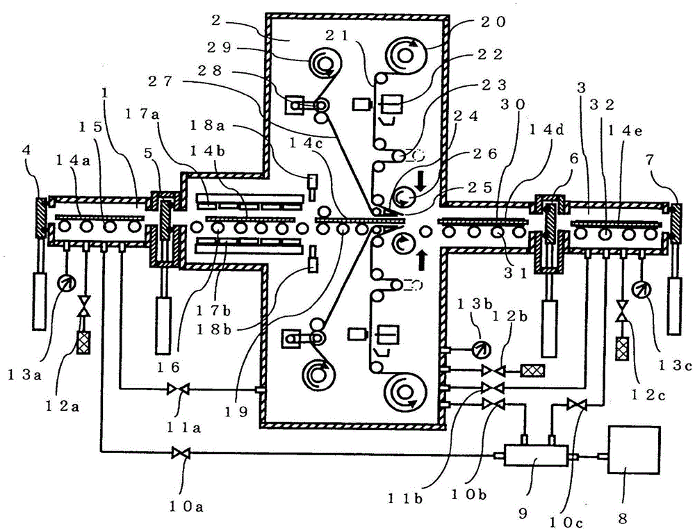
[0084] figure 1 This is an example of the vacuum lamination apparatus of the film of the present invention, and shows a state in which a laminated film is vacuum-laminated on both sides of a substrate, and shows the state immediately before lamination in the vacuum chamber 2 .

[0085] This film vacuum lamination device consists of an inlet chamber 1 for feeding substrates from air, a vacuum chamber 2 for preheating and laminating substrates in a vacuum, an outlet chamber 3 for carrying out substrates from vacuum chamber 2 to air, and a control system for these mechanisms. The configuration of the control device which is not shown in the figure. In addition, since the film lamination part in the vacuum chamber 2 is vertically symmetrical, the reference numeral of the lower side is abbreviate|omitted.

[0086] exist figure 1 In the fig...


PUM


Abstract

The present invention provides a vacuum laminating device for a film which can laminate in the high vacuum, for example the high vacuum of which the vacuum degree is below 0.5 kPa. In order to change the length of an pasted laminated film 21 correspondingly with the length of an input substrate 14a, the length of the substrate 14a is measured before lamination, and a film length adjusting mechanism 23 is comprised. The film length adjusting mechanism 23 changes the holding length of the laminated film 21 according to the measured length of the substrate 14a between a semi-cutting position and a blade part 24 nearby a lamination roller 26, at the length position of the pasted laminated film 24, the laminated film 21 of which the holding length is changed by the film length adjusting mechanism 23, and before a protection film 27 is peeled, is semi-cut, and the laminated film 21 is conveyed to the blade part 24 by utilizing a film conveying mechanism 20, 29 and under a state of connecting the laminated film via the protection film 27.

Description

technical field [0001] The present invention relates to a vacuum lamination apparatus for a film, and more particularly to a vacuum lamination apparatus for laminating a laminated film such as a photosensitive dry film for pattern formation to the surface of a printed circuit board in vacuum. Background technique [0002] Centering on mobile phones, etc., the technical innovation of printed circuit boards (in this specification, sometimes simply referred to as "substrates") is in a state of continuous progress, and in particular, miniaturization and weight reduction of substrates have become increasingly important issues. [0003] With regard to the miniaturization of the substrate, miniaturization of patterns formed on the substrate and multilayering of the substrate are progressing, and with respect to weight reduction of the substrate, thinning of the substrate is progressing. [0004] Here, pattern formation is mainly performed by a method called a photolithography proce...

Claims


Application Information

Patent Timeline
IPC IPC(8): B32B37/10B32B38/00B32B38/18
CPCB32B37/1018B32B38/0036B32B38/185B32B2309/68B32B2457/08
Inventor 高桥一雄大泽睦山本英树
Owner HITACHI PLANT MECHANICS
Why Eureka
Try Eureka