Excavator moving arm potential energy classified recovery and release device and method thereof

A technology of release device and motorized arm, applied in mechanically driven excavators/dredgers, earth movers/shovels, construction, etc., can solve the problems of reduced energy recovery rate, poor portability, and vehicle bumping, etc. Achieve the effect of improving energy saving efficiency, good self-locking performance and increasing volume

Active Publication Date: 2016-09-07
ZHEJIANG UNIV
View PDF7 Cites 13 Cited by
  • Summary
  • Abstract
  • Description
  • Claims
  • Application Information

AI Technical Summary

Problems solved by technology

[0004] (1) Recovery through the hydraulic control reversing valve: Due to the harsh working environment of the excavator, large load changes, and high requirements for energy recovery, it is impossible to judge whether the system is loaded by simply using the hydraulic control reversing valve to determine whether to perform energy recovery , and if the energy recovery system is turned on under load, the boom will drop rapidly due to the low pressure of the accumulator, resulting in a stall phenomenon
[0005] (2) Recovery through proportional directional valve, proportional throttle valve, and speed regulating valve: the introduction of proportional directional valve, proportional throttle valve, and speed regulating valve will bring certain throttling loss, reduce energy recovery rate, and The proportional signal needs to be matched with the excavator's working conditions, pose, etc., the control performance is complicated, and the portability is poor
[0006] Moreover, the existing research cannot solve the problem of energy recovery when the boom is lowered when the excavator is loaded. Once the boom is lowered when the excavator is loaded (for example, during the loading and unloading process, the boom will have a small displacement to adjust the optimal unloading method). Soil posture), because the bucket is filled with materials, the load increases a lot, and because the moment arm is longer, the pressure in the rodless cavity of the boom cylinder increases by about 6MPa compared with the empty load (taking a medium-tonnage excavator as an example ), at this time, if it is still recovered through the original accumulator, or the pressure of the accumulator is too low, the boom will drop rapidly when the energy is recovered. At this time, the speed cannot be controlled, and the forced braking will cause the whole vehicle to shake violently , the risk is high; and if the working pressure of the accumulator is increased to make the pressure of the accumulator equal to the pressure of the large chamber of the boom when it is loaded, it can solve the phenomenon of the boom falling quickly when it is lowered with a load, but it will Due to the high pressure of the accumulator, and because the descending speed becomes slower, the power of the main pump increases, which also offsets the energy recovery effect to a certain extent.
And by judging the pressure sensor to judge whether it is loaded, it is not feasible to recover when it is loaded, and it is not feasible to recover when it is controlled, because if the reversing valve is opened with a large opening, the pressure in the large cavity of the boom will drop rapidly. The pressure in the large cavity of the boom is about the same when it is loaded and not loaded, and it cannot be distinguished whether it is loaded or not, and if the energy is not recovered when it is loaded, the energy recovery rate will be reduced; and as mentioned above, using balance valves or speed control valves Flow elements are used to improve the rapid drop of the boom when descending with load, which will bring a certain pressure loss and reduce the energy recovery rate

Method used


Image

  • Excavator moving arm potential energy classified recovery and release device and method thereof

Examples


Embodiment Construction

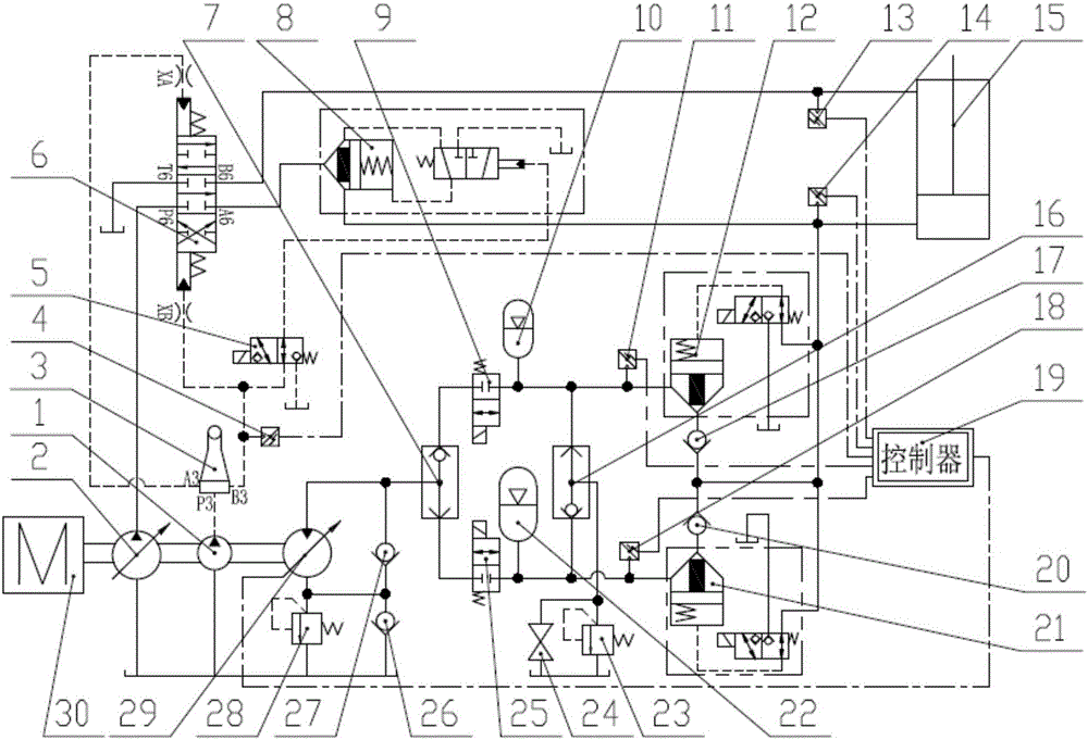
[0033] Attached below figure 1 Specific embodiments of the present invention will be described.

[0034] like figure 1 Shown, a boom potential energy classification recovery and release device. It mainly includes the pilot pump (1, the main pump (2), the operating handle 3, the first pressure sensor 4, the boom lock control valve 5, the hydraulic control reversing valve 6, the first shuttle valve 7, the boom lock Valve 8, low pressure release valve 9, low pressure accumulator 10, second pressure sensor 11, low pressure recovery valve 12, third pressure sensor 13, fourth pressure sensor 14, boom cylinder 15, second shuttle valve 16, first Check valve 17, fifth pressure sensor 18, controller 19, second check valve 20, high pressure recovery valve 21, high pressure accumulator 22, safety valve 23, stop valve 24, high pressure release valve 25, third check valve Valve 26 , fourth one-way valve 27 , back pressure valve 28 , auxiliary motor 29 , engine 30 .

[0035] The connecti...


PUM


Abstract

The invention discloses an excavator moving arm potential energy classified recovery and release device and a method thereof. The device comprises an engine, a pilot pump, a main pump, an operation handle, five pressure sensors, a moving arm locking control valve, a hydraulic control reverse valve, two shuttle valves, a moving arm locking main valve, two release valves, a moving arm locking pilot valve, two energy accumulators, two recovery valve moving arm oil cylinders, four one-way valves, a controller, a safety valve, a stop valve, a high-pressure release valve, a back pressure valve and an auxiliary motor. The device judges if a moving arm has a load through acquiring pressure signals in each point, so that the high-pressure energy accumulator is used for recovering the load when the moving arm is high in load, the low-pressure energy accumulator is used for recovering the load when the removing arm has no load, the potential energy of the moving arm under different working conditions can be totally recovered, and such defects as throttling loss caused by a traditional method or a proportional direction valve, a throttle valve and a speed adjusting valve, weak control characteristic by single energy accumulator and incapability of totally recovering the power reducing potential energy are prevented; and the device has such characteristics as high oil saving rate, good controllability and no influence on working efficiency of a traditional machine.

Description

technical field [0001] The invention relates to an excavator, in particular to a hydraulic system for recovering and releasing potential energy of an arm of an oil-liquid hybrid excavator, and belongs to the technical field of engineering machinery. Background technique [0002] The boom of the hydraulic excavator has the characteristics of frequent movement and large mass. During the lowering of the boom, a large amount of oil is wasted through the orifice of the main control valve, which not only causes energy loss but also reduces the life of the system due to the increase of oil temperature. By recovering and utilizing the potential energy of the boom, a secondary power source is formed, and a hybrid system is formed with the engine, which can significantly improve the fuel saving rate of the excavator. [0003] At present, the recovery and utilization of the potential energy of the boom is mainly concentrated in two aspects: one is to recover through the motor, and con...

Claims


Application Information

Patent Timeline
Patent Type & Authority Applications(China)
IPC IPC(8): E02F3/42E02F9/22
CPCE02F3/42E02F9/22
Inventor 魏建华郭凡方锦辉李宗张宏秦家升费树辉乔西宁谭贤文李明杰于欢王振兴金月峰
Owner ZHEJIANG UNIV
Why Eureka
Try Eureka