High-speed solenoid valve drive circuit for dual injectors of opposed two-stroke engines

A high-speed solenoid valve, drive circuit technology, applied in engine components, engine control, machine/engine and other directions, can solve problems such as large driving current pressure difference

Active Publication Date: 2018-08-28
CHINA NORTH ENGINE INST TIANJIN
View PDF10 Cites 0 Cited by
  • Summary
  • Abstract
  • Description
  • Claims
  • Application Information

AI Technical Summary

Problems solved by technology

[0004] In view of this, the present invention aims to propose a high-speed solenoid valve drive circuit for dual fuel injectors of an opposed two-stroke engine to solve the problem of a large pressure difference when the double fuel injectors work simultaneously.

Method used


Image

  • High-speed solenoid valve drive circuit for dual injectors of opposed two-stroke engines
  • High-speed solenoid valve drive circuit for dual injectors of opposed two-stroke engines
  • High-speed solenoid valve drive circuit for dual injectors of opposed two-stroke engines

Examples


Embodiment Construction

[0021] It should be noted that, in the case of no conflict, the embodiments of the present invention and the features in the embodiments can be combined with each other.

[0022] The present invention will be described in detail below with reference to the accompanying drawings and examples.

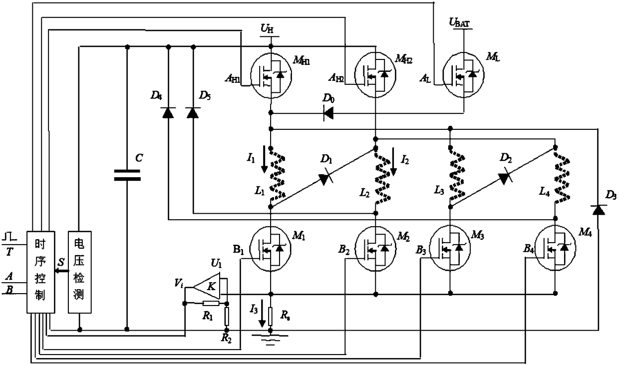
[0023] In the embodiment of the present invention, the high-speed solenoid valve driving circuit of the double fuel injector of the opposed two-stroke engine is used as a driving module for four high-speed solenoid valves of two cylinders A and B, and adopts the mode of double driving voltage and double driving current, wherein the four The inductance coils of two high-speed solenoid valves are respectively the inductance coils L of the high-speed solenoid valves of the two fuel injectors of cylinder A 1 , L 2 and the inductance coil L of the high-speed solenoid valve of the two injectors of cylinder B 3 , L 4 .

[0024] Such as figure 1 As shown, the high-speed solenoid valve drive...


PUM


Abstract

The invention provides a driving circuit for a dual-fuel-injector high-speed electromagnetic valve of an opposed two-stroke engine. The driving circuit comprises a timing sequence control module for driving two cylinders and four electromagnetic valves, a voltage detection module, switching diodes D1 and D2, an energy-storage capacitor C, three high-end MOS tubes MH1, MH2 and ML and four-end MOS tubes M1, M2, M3 and M4, wherein inductance coils of the four electromagnetic valves are respectively inductance coils L1 and L2 of two electromagnetic valves corresponding to the air cylinder A and inductance coils L3 and L4 of two electromagnetic valves corresponding to the air cylinder B. According to the invention, by means of the mode that a drive structure switches from parallel driving to tandem driving, and the form that driving high pressure of the electromagnetic valves is adopted for respective driving at an initial stage of current rising, so that the fact that currents of the electromagnetic valves rapidly rise to a target current is ensured; and a total current, borne on a circuit board, of the electromagnetic valves is equal to a current that one electromagnetic valve is driven during two subsequent states, namely a high current opening stage and a small current keeping stage.

Description

technical field [0001] The invention belongs to the technical field of driving high-speed electromagnetic valves of double fuel injectors, and in particular relates to a driving circuit of high-speed electromagnetic valves of double fuel injectors of opposed two-stroke engines. Background technique [0002] In the high-pressure common rail control of opposed two-stroke engines, the driving problem of high-speed solenoid valves of double injectors is one of the key technologies. [0003] Existing drives are carried out by using two power drive circuits to drive two solenoid valves. Since the double injectors need to work at the same time, the drive current will increase exponentially, and the drive lines on the printed cable board need to be arranged more The wide copper skin occupies a large space for the entire power drive part, which is not conducive to the compact design of the electronic control unit; at the same time, due to the large operating current and long duration...

Claims


Application Information

Patent Timeline
Patent Type & Authority Patents(China)
IPC IPC(8): F02D41/20F02M63/00
CPCF02D41/20F02D2041/2006F02D2041/2017F02D2041/2051F02D2041/2082F02M63/0017
Inventor 白思春褚全红孟长江贾利焦玉琴姜承赋和龙陈志瑞
Owner CHINA NORTH ENGINE INST TIANJIN
Why Eureka
Try Eureka