A remote well natural gas recovery device

A recovery device and natural gas technology, applied in the direction of gas processing applications, fixed-capacity gas storage tanks, equipment loaded into pressure vessels, etc., can solve the problems of time-consuming and laborious transportation, installation and disassembly, low transportation frequency, and no integration. , to achieve the effect of convenient and quick disassembly

Active Publication Date: 2018-07-17
SOUTHWEST PETROLEUM UNIV
View PDF7 Cites 0 Cited by
  • Summary
  • Abstract
  • Description
  • Claims
  • Application Information

AI Technical Summary

Problems solved by technology

[0004] However, the existing scattered natural gas CNG recovery devices have the following deficiencies: 1) Skids for heating, separation, filtration, dehydration, compression, metering, etc. are set separately without integration. It is placed on the foundation of the well site, and the connecting pipelines between the skids are all connected by steel pipes. The transportation, installation and disassembly of the whole set of equipment are time-consuming and laborious. It is only suitable for the recovery of high-pressure stable production remote wells with low transportation frequency. , not suitable for the recovery of scattered natural gas in intermittent wells with low output and frequent relocation; 2) The dehydration device of the existing recovery device does not have a bypass, and the recovered gas is only considered to be directly sold as CNG commercial gas or transported to natural gas The injection pipeline network of gas gathering stations, export stations and other gas fields cannot meet the actual needs of some gas fields. The recovery device can be sold as CNG commercial gas and injected into the pipeline network inside the gas field.

Method used


Image

  • A remote well natural gas recovery device
  • A remote well natural gas recovery device

Examples


Embodiment 1

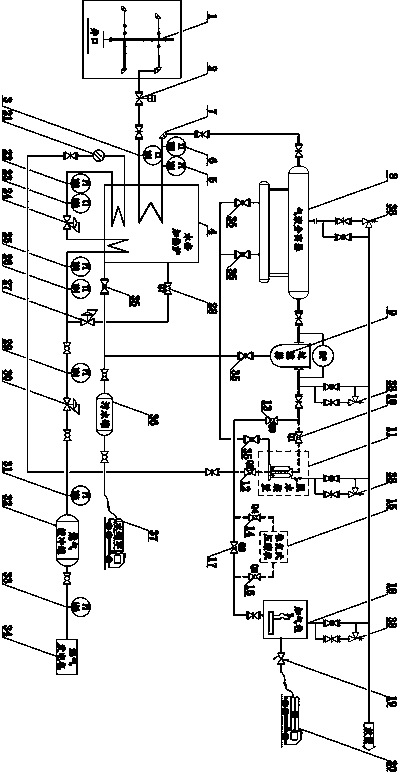
[0023] Such as figure 1 As shown, when the CNG recovered by this recovery device is directly sold as commercial gas and the wellhead pressure is lower than 20MPa or used for recovery of scattered natural gas in low temperature environments such as winter: the gas from the gas tree 1 is heated by the water jacket heating furnace 4 Enter the gas-liquid separator 8 for separation, and then filter through the first filter 9, the ball valve Q1 10 and the ball valve Q2 12 at both ends of the dehydration device 11 are opened, and the ball valve Q3 13 on the bypass pipeline is then closed, and the incoming air enters the dehydration device (11 ) to remove moisture in the natural gas, so that the water dew point of the natural gas is 5°C lower than the local minimum temperature at 20 MPa, the ball valves Q4 14 and Q5 16 at both ends of the reciprocating compressor (15) are opened, and the ball valves on the bypass pipeline Q6 17 is closed, and after dehydration, the natural gas is pres...

Embodiment 2

[0025] Such as figure 1As shown, when the CNG recovered by this recovery device is transported to the gas field gas gathering station and re-injected into the pipeline network and the wellhead pressure is lower than 20MPa: the gas from the gas tree 1 is heated by the water jacket heating furnace 4 and then enters the gas-liquid separator 8 Separated, then filtered by the first filter 9, the ball valve Q1 10 and ball valve Q2 12 at both ends of the dehydration device 11 are closed, the ball valve Q3 13 on the bypass line is opened, and the incoming air does not enter the dehydration device 11. Deep dehydration treatment, reciprocating compression The ball valve Q4 14 and ball valve Q516 at both ends of the machine 15 are opened, and the ball valve Q6 17 on the bypass pipeline is closed, and the incoming gas enters the reciprocating compressor 15 through the bypass pipeline of the dehydration device and is pressurized to 20MPa, and after being measured by the gas filling column 1...

Embodiment 3

[0027] Such as figure 1 As shown, when the CNG recovered by this recovery device is directly sold as commercial gas and the wellhead pressure is higher than 20MPa: the gas from the gas tree 1 is heated by the water jacket furnace 4 and then enters the gas-liquid separator 8 for separation, and then passes through the first The filter 9 is filtered, the ball valve Q1 10 and the ball valve Q2 12 at both ends of the dehydration device 11 are opened, and the ball valve Q3 13 on the bypass line is closed, and the incoming air enters the dehydration device 11 to remove the moisture in the natural gas, so that the water dew point of the natural gas is at At 20MPa, the temperature is 5°C lower than the local minimum temperature, the ball valve Q4 14 and ball valve Q5 16 at both ends of the reciprocating compressor (15) are closed, the ball valve Q6 17 on the bypass pipeline is opened, and the incoming gas does not pass through the reciprocating compressor 15 to increase directly throu...


PUM


Abstract

The invention provides a remote well natural gas recovery device which mainly comprises a water jacket heater, a gas-liquid separator, a filter, a dehydration device, a reciprocating compressor, a gas charging pillar, a gas generating set and the like, and is characterized in that gas generated from a remote well is heated by a heating furnace, the heated gas enters the gas-liquid separator and the filter for separation and filtering to remove a liquid phase and a solid phase via separation and filtration, the filtered product is dehydrated by a molecular sieve, the dehydrated product enters the reciprocating compressor, the compressed product is pumped into a CNG trailer after being measured by the gas charging pillar to serve as CNG commercial gas for sale; when the CNG trailer containing the recovered gas is driven to a gas gathering station of a gas field, and the recovered gas is pumped into a pipe network again, charged gas enters a by-pass of the dehydration device directly; when the pressure in a well mouth is equal to or higher than 20 MPa, the charged gas enters a by-pass of the compressor directly; fuel gas of the gas generating set and the water jacket heater is supplied through a rear process pipeline of the dehydration device; and the whole set of the remote well natural gas recovery device is mounted on two semi-trailers, and fixedly erected on a well field via a hydraulic jack. The remote well natural gas recovery device is suitable for recovery of scattered natural gas in high-yield or intermittent-production remote wells of different well mouth pressures; the moving, transportation and mounting are convenient and fast; the adaptive capacity is high; and the recovery cost is low.

Description

technical field [0001] The invention relates to a device for safe, efficient and low-cost recovery of scattered natural gas, shale gas, oilfield associated gas, etc., which are located remotely and have no economic benefits by pipeline collection and transportation, and are filled into a CNG long-tube trailer. It relates to a remote well natural gas recovery device and belongs to the field of natural gas gathering and transportation engineering. Background technique [0002] During the exploration and development of conventional natural gas fields and unconventional natural gas fields such as shale gas, due to the need to drill wells, evaluation wells and other reasons, it is inevitable to produce some scattered and remote single wells with low production and far away from the gas gathering station. . In addition, during the development of oilfields, some oilfield-associated gas will be produced from crude oil, and its main component is also CH4, but the output is low. Due...

Claims


Application Information

Patent Timeline
Patent Type & Authority Patents(China)
IPC IPC(8): F17C5/04F17C7/02F17C13/02F17C13/04F17C13/08
CPCF17C5/04F17C7/02F17C13/025F17C13/026F17C13/04F17C13/084F17C2221/033F17C2270/0168
Inventor 岑康贾敏姚婷李薇黄金明郑昕张优
Owner SOUTHWEST PETROLEUM UNIV
Why Eureka
Try Eureka