Laser composite texture thin-walled tube bending mold and composite texture forming method thereof

A technology of composite weaving and thin-walled tubes, which is applied in laser welding equipment, forming tools, manufacturing tools, etc., can solve the problems of uncontrollable changes in surface roughness, difficult lasting effects, adhesive wear, etc., and achieve wall thickness changes and Uniform cross-section deformation, improved material flow, precise and stable bending and forming effects

Active Publication Date: 2016-09-21
ZHENJIANG COLLEGE
View PDF11 Cites 5 Cited by
  • Summary
  • Abstract
  • Description
  • Claims
  • Application Information

AI Technical Summary

Problems solved by technology

However, the rough surface is easy to wear, and the above effects are difficult to last
Use the low-roughness die surface to reduce harmful friction, but the smooth surface is in a boundary lubrication state because there is no oil storage area, and mixed lubrication or fluid lubrication cannot be formed, which is prone to adhesive wear, easy to scratch, and the life of the die is reduced
On the other hand, the change of surface roughness by the above method is random and uncontrollable, and it is difficult to ensure the consistency of surface treatment, so that the above method always stays in the empirical stage

Method used


Image

  • Laser composite texture thin-walled tube bending mold and composite texture forming method thereof
  • Laser composite texture thin-walled tube bending mold and composite texture forming method thereof

Examples


Embodiment Construction

[0024] The laser composite textured thin-walled pipe bending mold and the method for forming the composite texture of the present invention will be further described in detail below with reference to the accompanying drawings and specific implementation methods.

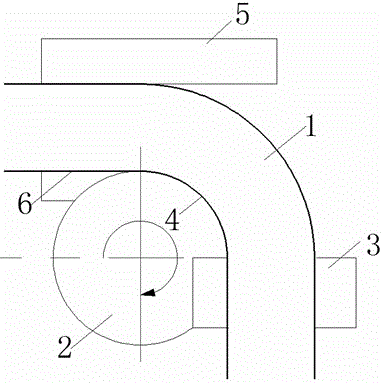
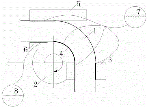
[0025] As shown in the figure, the laser composite texture thin-walled pipe bending mold of the present invention includes a pipe bending mold main body 2 corresponding to the bending part of the pipe 1, a clamping block 3 for clamping the vertical section of the pipe 1 and a In addition to pressing the briquetting block 5 on the horizontal section of the pipe material 1, it also includes an anti-wrinkle plate installed on one side of the main body of the pipe bending mold. The clamping surface of the bending die is provided with a composite shape on the clamping surface of the pipe bending die, and the composite shape includes a boss shape 7 and a pit shape 8, and the boss shape 7 and the pit shape 8 are distributed...


PUM

PropertyMeasurementUnit
heightaaaaaaaaaa
diameteraaaaaaaaaa
depthaaaaaaaaaa

Abstract

The invention discloses a laser composite texture thin-walled tube bending mold and a composite texture forming method thereof, and belongs to the field of machine manufacturing. The mold comprises a tube bending mold main body corresponding to a bent part of a tube, a clamping block used for being clamped on a vertical section of the tube and a pressing block used for being pressed on a horizontal section of the tube. The mold further comprises a wrinkle-proof plate mounted on one side of the tube bending mold main body. The clamping block, the pressing block, the wrinkle-proof plate and the arc-shaped surface of the tube bending mold main body form the clamping face of the tube bending mold. The clamping face of the tube bending mold is provided with composite shapes. By adopting the structure and the method, the strain distribution, variation of the wall thickness and deformation of cross sections of formed parts are more uniform; side tube walls are prevented from instability wrinkling due to large curvatures and too small thickness and drawing breakage due to small curvatures; and springback of the formed parts is alleviated, the tube bending precision is improved, and the forming quality is improved. Finally, bending forming with the stable precision is achieved.

Description

technical field [0001] The invention relates to a bent pipe forming die, in particular to a thin-walled pipe bending die with a laser composite texture and a method for forming the composite texture, belonging to the field of mechanical manufacturing. Background technique [0002] Theoretical and engineering studies have shown that the friction in metal plastic forming cannot be reduced blindly. The friction characteristics of the contact interface between the mold and the workpiece have different effects on the forming quality of the workpiece. Therefore, there are the most reasonable friction conditions at different contact interfaces. [0003] Existing technologies such as thermal spraying, plasma chemical heat treatment, vapor deposition, TD treatment, ion implantation, surface shot peening, etc., change the surface composition, geometry, structure or deposit coating on the surface of the mold to improve the hardness, wear resistance, Fatigue strength, heat resistance, c...

Claims


Application Information

Patent Timeline
Patent Type & Authority Applications(China)
IPC IPC(8): B21D37/10B23K26/352
CPCB21D37/10B23K26/352
Inventor 戴金跃
Owner ZHENJIANG COLLEGE
Why Eureka
Try Eureka