
Intelligent heat management system for engine and control method

A technology of intelligent thermal management and control method, applied in engine components, machine/engine, engine cooling, etc., can solve problems such as prolonged working hours, high failure rate of fans and control modules, and untimely cooling of fans. The effect of reducing fuel consumption

Active Publication Date: 2016-09-21
LONGKOU ZHONGYU THERMAL MANAGEMENT SYST SCIAND TECH
View PDF9 Cites 5 Cited by
  • Summary
  • Abstract
  • Description
  • Claims
  • Application Information

AI Technical Summary

Problems solved by technology

[0006] Conventional engine intelligent thermal management system domestic similar products use a single control program to constantly control the engine thermal management system, because it cannot meet the heat dissipation requirements of the engine when the ambient temperature changes in four seasons, and too much pursuit of low fuel consumption experimental data, so it is often used in market applications. Occurs: In summer, the water temperature is too high, and the fan does not dissipate heat in time; in winter, the water temperature is low, and the heating effect is poor. At the same time, due to the extended working hours of the fan and the control module, the failure rate of the fan and the control module remains high.
[0007] The reason: due to the low ambient temperature during winter installation, the control temperature setting is relatively high, which brings about the problem that the water temperature is too high in summer or under heavy load, and the fan cannot meet the heat dissipation requirements of the engine. On the contrary, if it is installed in summer , Debugging, the ambient temperature is high, the control temperature is set relatively low, and when used in winter, the ambient temperature is lower, so the heating effect is relatively poor, the fuel consumption increases, and the failure rate of the fan and the control module is high; If the ambient temperature is between winter and summer when installed in spring and autumn, the product will have both advantages and disadvantages of summer and winter

Method used


Image

  • Intelligent heat management system for engine and control method
  • Intelligent heat management system for engine and control method
  • Intelligent heat management system for engine and control method

Examples


Embodiment Construction

[0057] The present invention is described in detail below with reference to accompanying drawing and embodiment:

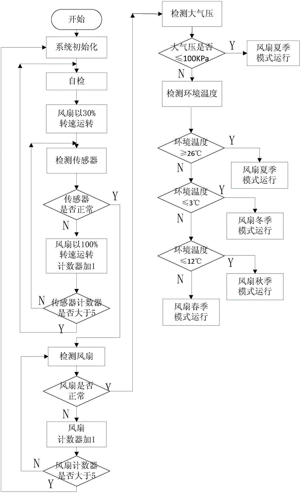
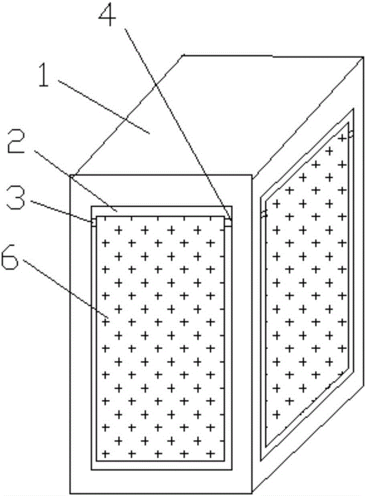
[0058] attached Figure 1-4 It can be seen that an engine intelligent thermal management system includes

[0059] Radiator, water pump, fan, cooling water jacket and cooling system temperature sensor;

[0060] The cooling system temperature sensor includes a cooling system sensor including an engine coolant temperature sensor, an intercooler intake air temperature sensor, and a torque converter oil temperature sensor; the engine coolant temperature sensor includes a first temperature sensor set on the engine body or on the cooling pipeline sensor and the second temperature sensor arranged on the radiator of the engine; the intercooler intake air temperature sensor includes three sensors arranged on the intercooler body and the fourth sensor arranged on the air intake pipeline of the engine, and also includes ambient temperature sensor and barometric pressure sen...


PUM


Abstract

The invention relates to an intelligent heat management system for an engine and a control method. The intelligent heat management system comprises an engine cooling liquid temperature sensor, an inter-cooling air inlet temperature sensor and a torque converter oil temperature sensor. The engine cooling liquid temperature sensor comprises a first temperature sensor and a second temperature sensor, wherein the first temperature sensor is arranged on an engine body or a cooling pipeline, and the second temperature sensor is arranged on a radiator of the engine. The inter-cooling air inlet temperature sensor comprises a third sensor arranged on an inter-cooler body and a fourth sensor arranged on an air inlet pipeline of the engine. The intelligent heat management system further comprises an environment temperature sensor and an atmosphere pressure sensor. The intelligent heat management system for the engine comprises control programs corresponding to four seasons of the year in a one-to-one manner, and the rotating speed of a cooling fan is controlled according to the environment temperature and the actual temperature of a cooling system. The system intelligently matches the optimal control through automatic monitoring of the environment temperature change, and the fuel oil consumption is greatly reduced on the premise that it is guaranteed that the heat dissipation requirement of the engine is met.

Description

technical field [0001] The invention relates to an engine temperature control system, in particular to an engine intelligent thermal management system and a control method. Background technique [0002] Vehicles and construction machinery will generate a lot of heat during their work. Due to changes in the working environment and working conditions, the heat generated will also change accordingly. In order to maintain the normal operation of the equipment, various coolers or heat exchangers are usually used to dissipate the heat to the environment by means of forced cooling by cooling fans. , so as to keep each device within the operating range of normal temperature. In the traditional cooling system, the cooling fan is usually installed on the engine. The change of the fan speed is corresponding to the change of the engine speed. The cooling effect is directly related to the engine speed. Therefore, the cooling system cannot meet all the working conditions of the system. ...

Claims


Application Information

Patent Timeline
Patent Type & Authority Applications(China)
IPC IPC(8): F01P5/02F01P7/04
CPCF01P5/02F01P7/048F01P2025/13F01P2050/22
Inventor 王兆宇邢子义李殿贇邢宗跃
Owner LONGKOU ZHONGYU THERMAL MANAGEMENT SYST SCIAND TECH
Learn More