A drag reduction device and method for injecting foam into heavy oil in spiral slots

A drag reduction device and spiral groove technology, applied in gas/liquid distribution and storage, pipeline systems, mechanical equipment, etc., can solve problems such as increased process, large energy consumption, pipeline corrosion, etc., to facilitate replacement and maintenance, and avoid direct contact. , the effect of increasing liquidity

Inactive Publication Date: 2017-12-15
SOUTHWEST PETROLEUM UNIV
View PDF7 Cites 0 Cited by
  • Summary
  • Abstract
  • Description
  • Claims
  • Application Information

AI Technical Summary

Problems solved by technology

Since the viscosity of crude oil decreases with the increase of temperature, its viscosity can be reduced by heating. Generally, mines use water jacket furnace heating or electric heat tracing heating, which requires high equipment investment and consumes a lot of energy for operation.
Using heating and viscosity-reducing pipelines, if you want to start, you must first preheat the pipeline with other light oil products, and then feed heavy oil; if you want to stop the pipeline, you must also replace heavy oil with other light oil products, resulting in a certain amount of waste , and the process is complicated, the safety reliability and flexibility are not high
Dilution is mainly done by adding light oil or back-mixing hot sewage. Adding light oil to heavy oil has a great impact on the quality of heavy oil. It also requires a reliable source of light oil in the mine, and heating sewage not only consumes a lot of heat energy, but also requires Separation of water in heavy oil, increasing the process
Chemical drag reducers have certain toxicity and are easy to pollute the environment, and drag reducers are often not universal. Most drag reducers are acidic and have certain corrosion on pipelines

Method used


Image

  • A drag reduction device and method for injecting foam into heavy oil in spiral slots
  • A drag reduction device and method for injecting foam into heavy oil in spiral slots
  • A drag reduction device and method for injecting foam into heavy oil in spiral slots

Examples


Embodiment

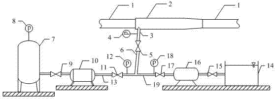
[0027] First, combine the flow characteristics of the heavy oil and the actual working conditions on site to determine the specific pipe section that needs to be installed with the device of the present invention. The device is composed of a skid, and only the bubble injector 2 needs to be installed in the form of a short connection on the heavy oil pipeline 1. , It can be fixed with the upstream and downstream pipelines through threaded connection.

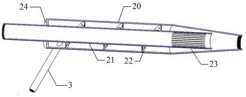
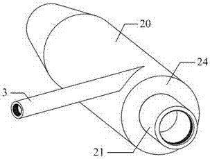
[0028]The gas injection unit and the water injection unit respectively provide the mixed gas source and water source for the bubble injector 2. The mixing flow and pressure of gas and water are determined by the water pump 16, the frequency of the gas compressor 10, the water injection valve 17, the gas injection valve 11, and the inlet valve. 5 adjustments. Gas and water are initially mixed in the gas-liquid mixing pipe 6, and then enter the annular space of the bubble injector 2 through the tangential injection pipe 3. Under t...


PUM


Abstract

The invention relates to a thick oil flowing resistance reducing device and method by injecting foam from a screw groove hole. The testing device consists of a foam resistance reducing unit, an air injecting unit and a water injecting unit which are skid-mounted, wherein a foam injector just needs to be mounted on a thick oil pipeline in a short connecting manner, and is fixed to an upper pipeline and a lower pipeline through screw connection. Gas phase-liquid phase fluid generates rich foam under the effect of rotary fluid guiding of a screw hole plate and fluid passage induced by a circular hole; the foam occupies the space of the thick oil pipeline close to an edge layer of the surface of the wall, and thick oil is forced to be separated from the wall of the pipe, so that the flow resistance in the pipeline is greatly reduced. The thick oil flowing resistance reducing device and method by injecting foam from the screw groove hole disclosed by the invention adopt a physical resistance reducing method, the purpose of flowing resistance reducing is realized without using chemical resistance-reducing agents and heating equipment, so that the environment is free from pollution. The thick oil flowing resistance reducing device disclosed by the invention is low in cost, safe and reliable, convenient to disassemble and assemble, and later stage changing and maintenance are convenient.

Description

technical field [0001] The invention relates to a flow drag reduction device and method for injecting foam into thick oil in spiral slot holes, belonging to the field of oil and gas gathering and transportation. Background technique [0002] The heavy oil in some oilfields in my country has a high content of colloid and asphaltene, and has the characteristics of high viscosity, high wax content, high freezing point, and poor fluidity, which makes the flow resistance relatively large during the transportation process, and often requires a high-power oil pump to pressurize or Heated transportation consumes more heat energy and kinetic energy, which increases the transportation cost. If there is a temporary suspension, the temperature of the heavy oil will gradually decrease. When the temperature drops below the wax precipitation point, a large number of wax crystals will precipitate, which not only greatly hinders the flow of the heavy oil, but also blocks the pipeline, resulti...

Claims


Application Information

Patent Timeline
Patent Type & Authority Patents(China)
IPC IPC(8): F17D1/17
CPCF17D1/17
Inventor 朱红钧尤嘉慧
Owner SOUTHWEST PETROLEUM UNIV
Why Eureka
Try Eureka