
Prediction method of forecabin thermal protection system whole trajectory temperature boundary of hypersonic velocity aircraft

A technology of hypersonic speed and prediction method, applied in the direction of instruments, special data processing applications, electrical digital data processing, etc., can solve problems such as insufficient accuracy, high cost, and occurrence of ablation deformation, so as to improve wing performance and safety performance, avoiding loss of precision, and improving computational efficiency

Active Publication Date: 2016-09-21
BEIHANG UNIV
View PDF3 Cites 34 Cited by
  • Summary
  • Abstract
  • Description
  • Claims
  • Application Information

AI Technical Summary

Problems solved by technology

Its disadvantage is one-time use, high cost, and ablation deformation
Among them, interval Taylor expansion and interval perturbation expansion are applied to strong nonlinear problems such as thermal radiation, and there is a problem of insufficient accuracy. Monte Carlo simulation has the defect that the amount of calculation is too large, and it is difficult to apply to practical engineering problems.

Method used


Image

  • Prediction method of forecabin thermal protection system whole trajectory temperature boundary of hypersonic velocity aircraft
  • Prediction method of forecabin thermal protection system whole trajectory temperature boundary of hypersonic velocity aircraft
  • Prediction method of forecabin thermal protection system whole trajectory temperature boundary of hypersonic velocity aircraft

Examples


Embodiment Construction

[0035] The present invention will be further described below in conjunction with the accompanying drawings and specific embodiments.

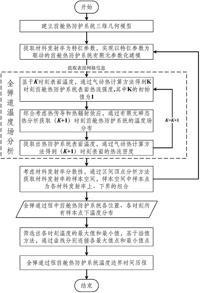
[0036] Such as figure 1 As shown, the present invention proposes a method for predicting the full trajectory temperature boundary of the aircraft front cabin thermal protection system, which specifically includes the following steps:

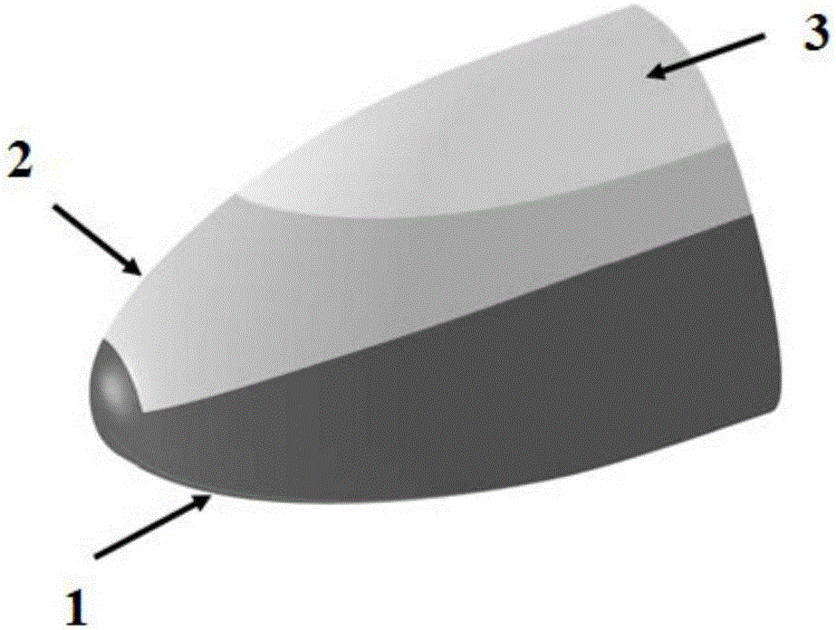
[0037] Step (1), according to the typical layout characteristics of the front cabin thermal protection system of a hypersonic vehicle, establish a three-dimensional geometric model of the thermal protection system, in which carbon / carbon heat-resistant materials are laid on the high-temperature areas such as the head and the windward side, and flexible insulation materials are laid on the low-temperature area on the leeward side. Heat felt, and rigid ceramic heat-resistant tiles are laid in other areas. Therefore, the front cabin thermal protection system involves 3 kinds of materials;

[0038]Step (2), transfo...


PUM


Abstract

The invention discloses a prediction method of the forecabin thermal protection system whole trajectory temperature boundary of a hypersonic velocity aircraft. The prediction method comprises the following steps: 1) according to the layout features of the forecabin thermal protection system of the hypersonic velocity aircraft, establishing a three-dimensional geometric model of the thermal protection system; 2) extracting the thermal conductivity coefficient and the emissivity of each material as feature parameters, and finishing the parametric establishment of a forecabin thermal protection system finite element model which takes the feature parameters as driving; 3) on the basis of the whole trajectory reentry process flight working condition of the aircraft, comprehensively considering thermal conductivity and thermal radiation effects to realize the transient thermal analysis of the thermal protection system in a whole trajectory process; and 4) considering material dispersibility, taking the thermal conduction coefficient and the emissivity of the material as uncertain input parameters, and finishing the analysis of the thermal protection system whole trajectory temperature boundary in the trajectory process on the basis of an interval vertex analysis method. The prediction method accurately and efficiently predicts the forecabin thermal protection system temperature boundary in the harsh reentry environment of the hypersonic velocity aircraft, and lays a foundation for the subsequent reliability rational evaluation and the uncertain optimization design of the structure.

Description

technical field [0001] The invention relates to the field of thermal analysis of hypersonic aircraft, in particular to a method for predicting the full trajectory temperature boundary of a front cabin thermal protection system of a hypersonic aircraft. Background technique [0002] The hypersonic vehicle thermal protection system is a structure used to protect the hypersonic vehicle from burning and overheating in the aerodynamic heating environment. High-speed aircraft include launch vehicles, spacecraft, and other vehicles that can reach near space. The heat protection structure is to keep the temperature of the inner wall of the hypersonic vehicle within the acceptable range of operation through heat insulation and heat dissipation measures. For the hypersonic spacecraft currently being developed in various countries, the thermal protection system is one of the key components, which can protect the vehicle from being safely loaded in a complex aerodynamic heating environ...

Claims


Application Information

Patent Timeline
Patent Type & Authority Applications(China)
IPC IPC(8): G06F17/50
CPCG06F30/23G06F2119/08
Inventor 王晓军王睿星王磊陈贤佳耿新宇
Owner BEIHANG UNIV
Learn More