Deep-sea drilling gas cut detection signal processing method and processing circuit

A technology for detecting signals and deep-sea drilling, applied in image data processing, instrument, character and pattern recognition, etc., can solve problems such as difficulties, lack of real-time effects, and lag in gas intrusion detection, achieving high speed, eliminating load effects, feasible effect

Active Publication Date: 2016-09-21
CHINA NAT OFFSHORE OIL CORP +1
View PDF3 Cites 3 Cited by
  • Summary
  • Abstract
  • Description
  • Claims
  • Application Information

AI Technical Summary

Problems solved by technology

[0002] In the process of offshore oil drilling, the principle of ultrasonic Doppler is used to measure the flow velocity and detect the gas content. When the ultrasonic Doppler is used to measure the flow velocity, the amplitude and frequency related signals of the flow velocity and Doppler signal are obtained, but this The signal is not a single standard Doppler frequency shift signal. Due to the randomness of the signal itself, it is difficult to analyze useful signals from such signals. Therefore, it is difficult to obtain accurate flow velocity results by using ultrasonic Doppler to measure flow velocity.
When ultrasonic Doppler is used to detect gas content, although the amplitude and frequency related signals of gas content and Doppler signal can be obtained, since the gas intrusion detection work is carried out in the deep sea area several kilometers underwater, if the detected The transmission of random signals to the road for processing will cause the air intrusion detection to lag behind. Therefore, in the deep sea, it cannot be processed by computer software like on land, and thus the real-time effect cannot be achieved.

Method used


Image

  • Deep-sea drilling gas cut detection signal processing method and processing circuit
  • Deep-sea drilling gas cut detection signal processing method and processing circuit
  • Deep-sea drilling gas cut detection signal processing method and processing circuit

Examples


Embodiment Construction

[0019] The present invention will be described in detail below in conjunction with the accompanying drawings and embodiments.

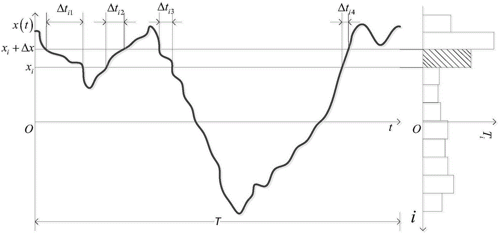
[0020] Amplitude domain analysis of random signals is an important part of statistical analysis of random signals. The probability that the amplitude of random signals falls within a specified interval can be expressed by the probability density function of random signals. Such as figure 1 As shown, the amplitude x(t) of the random signal falls in the amplitude interval of the i-th layer (x i ,x i The time value within +Δx) is T i , time value T i The calculation formula is as follows:

[0021] T i = Δt i 1 + Δt i 2 + ... + Δt iN i = ...


PUM


Abstract

The invention relates to a deep-sea drilling gas cut detection signal processing method and a processing circuit. The method comprises the following steps: (1) a to-be-processed random signal amplitude measurement range is equally divided into m layers of amplitude intervals, and m reference levels are set according to the to-be-processed random signal amplitude measurement range and the m layers of amplitude intervals and are correspondingly offered to m stages of parallel comparators; (2) the m stages of parallel comparators receive the m reference levels and a to-be-detected signal, and output m comparison output signals; (3) exclusive OR processing is carried out on two adjacent comparison output signals to get a hierarchical signal containing the time width for the amplitude of the to-be-detected signal falling into each layer of amplitude interval and the information about the number of occurrences of the time width, and the time value for the amplitude of the to-be-detected signal falling into each amplitude interval within an observation time value and the value of total number of occurrences are acquired through statistical analysis and uploaded to a computer; and (4) the computer draws an average speed distribution histogram and an amplitude probability distribution diagram according to the time value for the amplitude of the to-be-detected signal falling into each amplitude interval within an observation time value and the value of total number of occurrences. Through the method and the circuit, fast and real-time analytic processing of random signals is realized.

Description

technical field [0001] The invention relates to the field of random signal analysis, in particular to a deep-sea drilling gas invasion detection signal processing method and processing circuit. Background technique [0002] In the process of offshore oil drilling, the principle of ultrasonic Doppler is used to measure the flow velocity and detect the gas content. When the ultrasonic Doppler is used to measure the flow velocity, the amplitude and frequency related signals of the flow velocity and Doppler signal are obtained, but this The signal is not a single standard Doppler frequency shift signal. Due to the randomness of the signal itself, it is difficult to analyze useful signals from such signals. Therefore, it is difficult to obtain accurate flow velocity results by using ultrasonic Doppler to measure flow velocity. . When ultrasonic Doppler is used to detect gas content, although the amplitude and frequency related signals of gas content and Doppler signal can be obt...

Claims


Application Information

Patent Timeline
IPC IPC(8): G06K9/00G06T11/00
CPCG06T11/00G06T2207/10132G06F2218/00
Inventor 何玉发蒋世全赵辉古军周建良李迅科谢彬周权高飞李峰飞郝希宁
Owner CHINA NAT OFFSHORE OIL CORP
Why Eureka
Try Eureka