
DC/DC converter topology circuit for high voltage switching power supply

A high-voltage switch and topology circuit technology, which is applied in the direction of adjusting electrical variables, output power conversion devices, converting DC power input to DC power output, etc., can solve problems such as increased power loss, low reliability, and increased number of switching tubes, etc. Achieve the effect of reducing the number of devices, simple topology structure, and high reliability

Inactive Publication Date: 2016-09-21
ZHEJIANG UNIV
View PDF3 Cites 3 Cited by
  • Summary
  • Abstract
  • Description
  • Claims
  • Application Information

AI Technical Summary

Problems solved by technology

The bridge conversion circuit has the advantages of bidirectional excitation of the transformer and is easy to achieve high power, but at the same time the bridge conversion circuit needs soft start, and there is a direct problem, and the reliability is low
[0003] The forward conversion circuit is also a common isolation conversion circuit, which has the advantages of simple circuit and high reliability. However, the forward conversion circuit transformer is single-phase excited and the utilization rate is low, so it is only suitable for small and medium power supplies.
The subsequent dual-transistor forward conversion circuit reduces the voltage stress of each switch tube and creates conditions for the development of high-voltage input forward converters. However, since the forward conversion circuit requires remagnetization, the duty cycle is limited to 0.5. the following
In response to this problem, a combined dual-transistor forward conversion circuit composed of multiple dual-transistor forward converters connected in parallel or in series has appeared, so that the equivalent duty cycle of the converter can be higher than 0.5, but the combination of these conversion circuits makes the switch The number of tubes is doubled, which increases the power loss and increases the difficulty of control

Method used


Image

  • DC/DC converter topology circuit for high voltage switching power supply
  • DC/DC converter topology circuit for high voltage switching power supply
  • DC/DC converter topology circuit for high voltage switching power supply

Examples


Embodiment Construction

[0020] Below in conjunction with accompanying drawing and embodiment the present invention is further described:

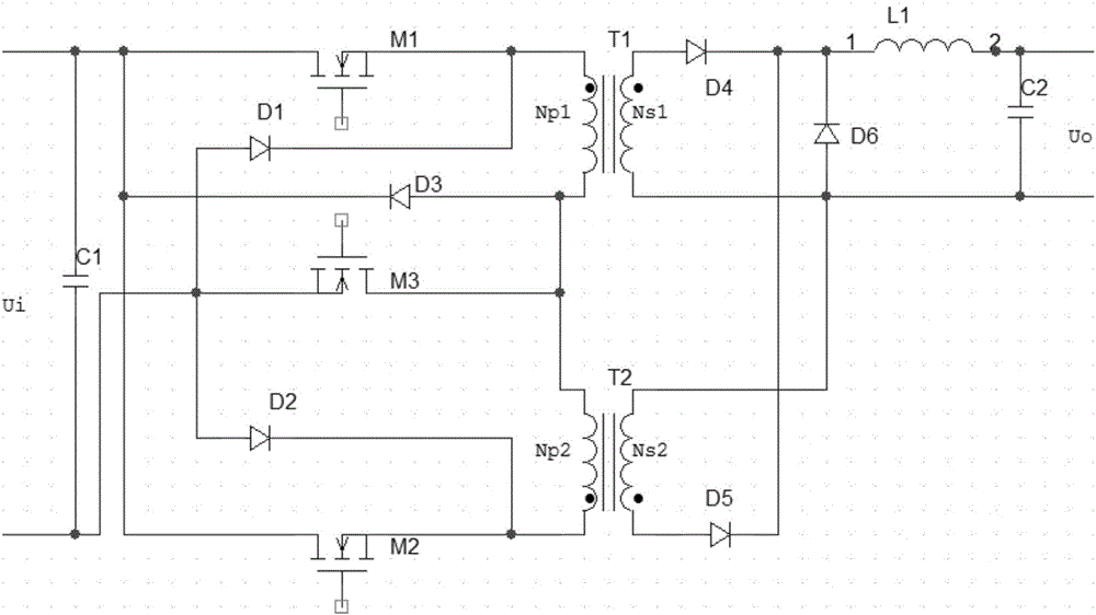
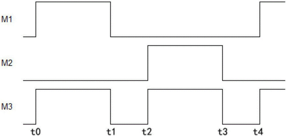
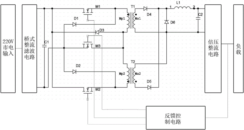
[0021] as attached figure 1 As shown, the DC / DC conversion circuit is composed of two forward conversion circuits connected in parallel on the primary side and the secondary side, and one of the switch tubes is shared on the primary side. The conversion circuit consists of an input capacitor C1, a first switching tube M1, a second switching tube M2, a third switching tube M3, a first magnetic reset diode D1, a second magnetic reset diode D2, a third magnetic reset diode D3, and a first rectifier diode D4, a second rectifier diode D5, a freewheeling diode D6, a first transformer T1, a second transformer T2, an output filter inductor L1, and an output filter capacitor C2. The first transformer T1 is composed of the first primary winding Np1 and the first secondary winding Ns1, and the second transformer T2 is composed of the second primary winding Np2 and the secon...


PUM


Abstract

The invention discloses a DC / DC converter topology circuit for high voltage switching power supply. The circuit comprises two forward-conversion circuits with an identical circuit structure; and the primary sides of the two forward conversion circuits are connected in parallel while the secondary sides are connected in parallel. With such a design, both the current outputting capacity and the outputted power are doubled, and at the same time, as the primary sides of the forward conversion circuits share the same switch tube, the circuit becomes suitable for high-voltage inputting. With a smaller number of devices, the circuit of the invention has a simple topology structure and can be manufactured at a low cost. Consuming less, the circuit achieves higher efficiency. Free of circuit magnetic polarization and straight-through problems, the devices are not easy to damage, making the circuit especially suitable for high voltage applications.

Description

technical field [0001] The invention relates to a DC / DC conversion topology circuit, in particular to a DC / DC conversion topology circuit of a high-voltage switching power supply. Background technique [0002] In switching power supply technology, the DC / DC conversion circuits commonly used are as follows: flyback, forward, half-bridge, full-bridge, push-pull, etc. On this basis, a variety of switching regulated power supply conversions are derived Circuits, such as dual-tube forward conversion circuits, etc. Since the voltage stress of the switching tube in the bridge conversion circuit is only half of the input voltage, the current high-voltage switching power supply mostly uses a bridge conversion circuit. The bridge conversion circuit has the advantages of two-way excitation of the transformer and easy to achieve high power, but at the same time, the bridge conversion circuit needs soft start, and there is a direct problem, and the reliability is low. [0003] The forw...

Claims


Application Information

Patent Timeline
IPC IPC(8): H02M3/335
CPCH02M3/3353H02M3/33592
Inventor 王剑平李艺健陈小天
Owner ZHEJIANG UNIV
Learn More